Disk drive adjusting gain of shock detector relative to resonant frequency amplitude

Inactive Publication Date: 2010-12-14
WESTERN DIGITAL TECH INC
View PDF17 Cites 115 Cited by
  • Summary
  • Abstract
  • Description
  • Claims
  • Application Information

AI Technical Summary

Problems solved by technology

Physical shocks to the disk drive may cause the head to deviate from the target track and corrupt data recorded in an adjacent track during a write operation.
Therefore, if a physical shock is detected using a suitable sensor (e.g., an accelerometer), the writ

Method used


Image

  • Disk drive adjusting gain of shock detector relative to resonant frequency amplitude
  • Disk drive adjusting gain of shock detector relative to resonant frequency amplitude
  • Disk drive adjusting gain of shock detector relative to resonant frequency amplitude

Examples


Embodiment Construction

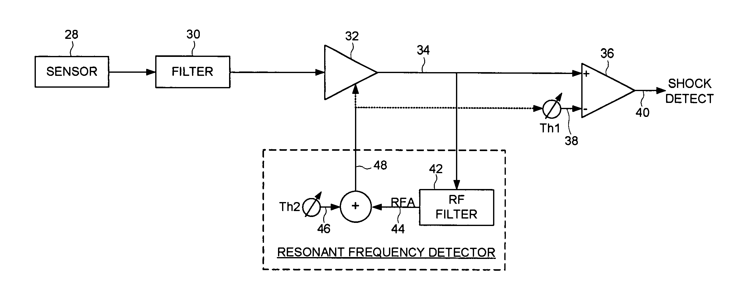
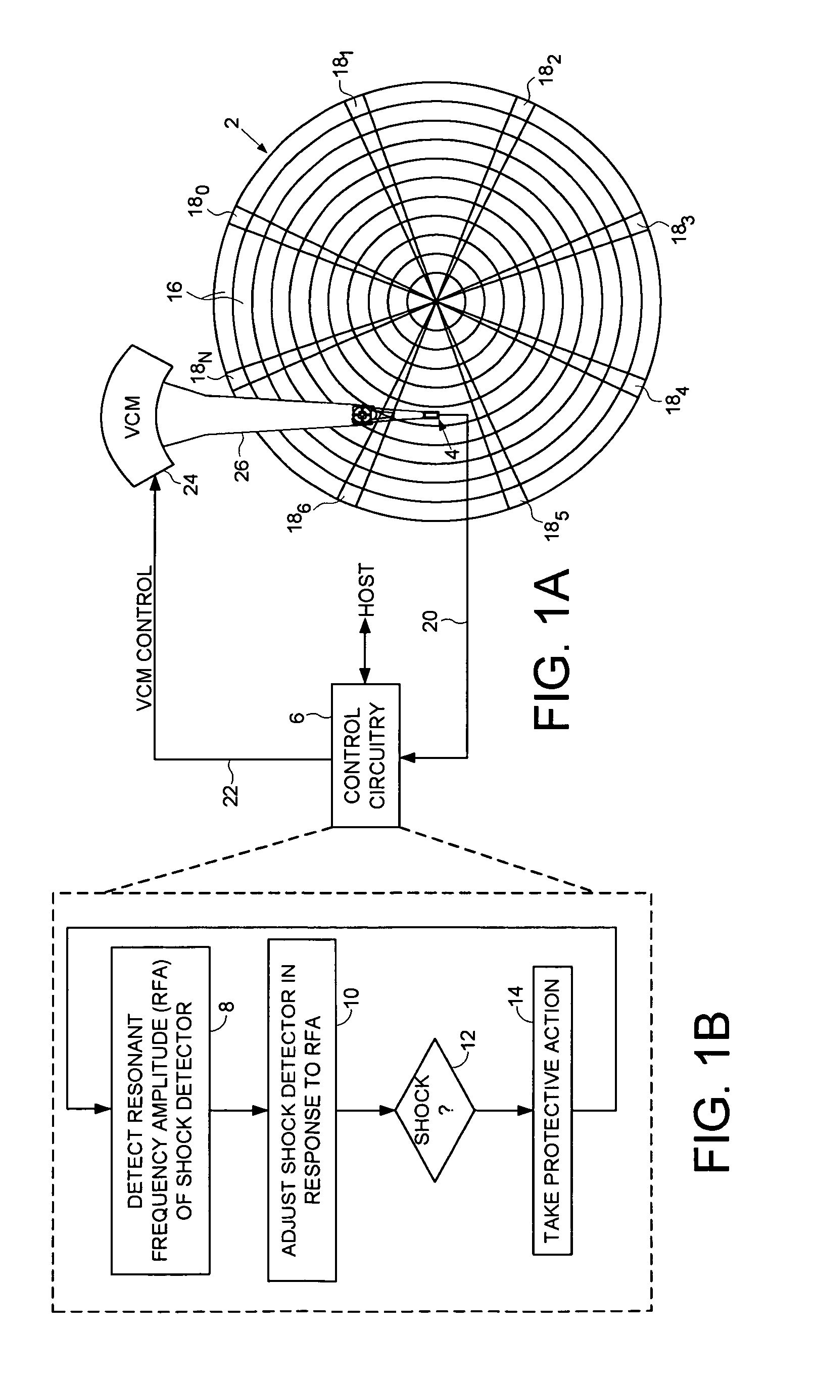
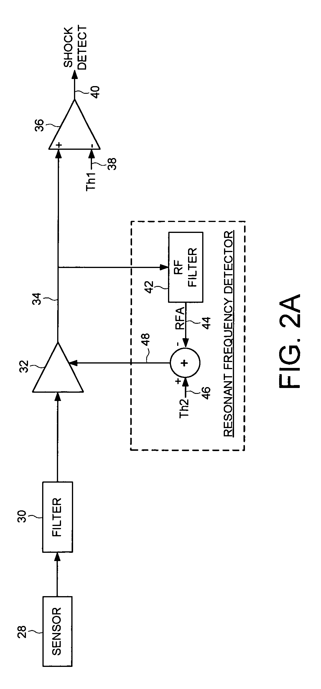
[0009]FIG. 1A shows a disk drive according to an embodiment of the present invention comprising a disk 2, a head 4 actuated radially over the disk 2, and control circuitry 6 including a shock detector. The control circuitry 6 executes the flow diagram of FIG. 1B in order to adjust the shock detector by detecting a resonant frequency amplitude (RFA) of the shock detector (step 8), adjusting the shock detector in response to the RFA (step 10), and taking protective action (step 14) when a shock event is detected (step 12).

[0010]In the embodiment of FIG. 1A, the disk 2 comprises a plurality of data tracks 16 defined by a plurality of embedded servo sectors 180-18N. The control circuitry 6 processes a read signal 20 emanating from the head 4 in order to demodulate the position information recorded in the embedded servo sectors 180-18N (e.g., a servo track address and servo bursts). The control circuitry 6 generates a position error signal (PES) representing a position error between a cu...


PUM


Abstract

A disk drive is disclosed comprising a disk, a head actuated radially over the disk, and control circuitry including a shock detector. The control circuitry is operable to detect a resonant frequency amplitude (RFA) of the shock detector, adjust the shock detector in response to the RFA, and take protective action in response to the shock detector.

Description

BACKGROUNDDescription of the Related Art[0001]A disk drive comprises a disk rotated by a spindle motor, and a head connected to a distal end of an actuator arm which is rotated about a pivot by a voice coil motor (VCM) to position the head radially over the disk. The disk comprises a number of concentric data tracks each partitioned into a number of data sectors. Access operations are performed by seeking the head to a target data track, and performing a write / read operation on the data sectors within the data track. The disk comprises embedded servo sectors having position information recorded therein, such as coarse position information (e.g., a track address) and fine position information (e.g., servo bursts). Control circuitry processes the read signal emanating from the head in order to demodulate the servo sectors into a control signal applied to the VCM in order to position the head over the target data track.[0002]Physical shocks to the disk drive may cause the head to devia...

Claims


Application Information

Patent Timeline
IPC IPC(8): G11B19/04
CPCG11B5/5582G11B5/596G11B19/042G11B5/59694
Inventor FERRIS, TIMOTHY A.RYAN, ROBERT P.
Owner WESTERN DIGITAL TECH INC
Why Eureka
Try Eureka