Fixing structure for an auxiliary lens of cameras

a technology for fixing structures and auxiliary lenses, which is applied in the field of auxiliary lenses for compact cameras, can solve the problems of inability to provide a function of close-up photography or macro-photography, bulky and expensive slr, and operate well when being connected to the camera properly, so as to reduce manufacturing costs, enhance the tightness between the camera body and the auxiliary lens, and enhance the effect of tightness

Inactive Publication Date: 2010-12-14
LUMOS TECH
View PDF5 Cites 36 Cited by
  • Summary
  • Abstract
  • Description
  • Claims
  • Application Information

AI Technical Summary

Benefits of technology

[0010]The present invention is to provide a fixing structure for an auxiliary lens of a camera. An abutting base is provided in the auxiliary lens, whereby the tightness between the camera body and the auxiliary lens can be enhanced when the camera body is combined with the auxiliary lens by rotation. Further, the degree of detaching the auxiliary lens from the camera body will not be affected.
[0011]The present invention is to provide a fixing structure for an auxiliary lens of a camera, in which a detachable and simple structure is used to replace the traditional expensive metallic elements, thereby reducing the cost of manufacturing and replacing the elements.
[0012]The present invention includes an annular base, an annular lens mount and an annular abutting base. The inner edge of the base protrudes upwardly to form a wall. The wall protrudes outwards to form a plurality of blocks. The inner edge of the lens mount is provided with a plurality of notches corresponding to the blocks. A first end surface of the abutting base extends to form a plurality of L-shaped elastic arms corresponding to the blocks and notches. The L-shaped elastic arm extends obliquely from the first end surface toward the lens mount. A gap is formed between the L-shaped elastic arm and the abutting base, so that the L-shaped elastic arm can be bent inwardly when compressed. When the camera is combined with the auxiliary lens by rotation, the block passes through the notch to abut and compress the L-shaped elastic arm. At the same time, the L-shaped elastic arm generates a reaction force, thereby enhancing the tightness between the camera body and the auxiliary lens.

Problems solved by technology

The minimum focus distance is more than 50 cm, so that such a compact camera cannot provide a function of close-up photography or a macro-photography.
Therefore, if a user needs a close-up photography or a macro-photography, he / she has to use a bulky-and-expensive SLR camera or attach an auxiliary lens with the desired specification to the front of original lens of the compact digital camera.
However, even though a high-quality lens is selected, it can only operate well when being connected to the camera properly.
Therefore, in addition to the quality of the auxiliary lens and the camera, it is also an important issue to connect this auxiliary lens and the camera firmly and accurately.
However, since the spring is formed with a plurality of windings in a coil, its volume cannot be reduced easily and thus it is not suitable for a compact camera.
After being used for a long time, the spring may suffer elastic fatigue, so that the damaged elements should be replaced frequently.
Since the cost of replacing metallic elements is larger, it becomes an additional burden for the user.
The volumes of the base and the auxiliary lens of such a fixing means are usually not small, so that it is not suitable for the compact camera.

Method used


Image

  • Fixing structure for an auxiliary lens of cameras
  • Fixing structure for an auxiliary lens of cameras
  • Fixing structure for an auxiliary lens of cameras

Examples


Embodiment Construction

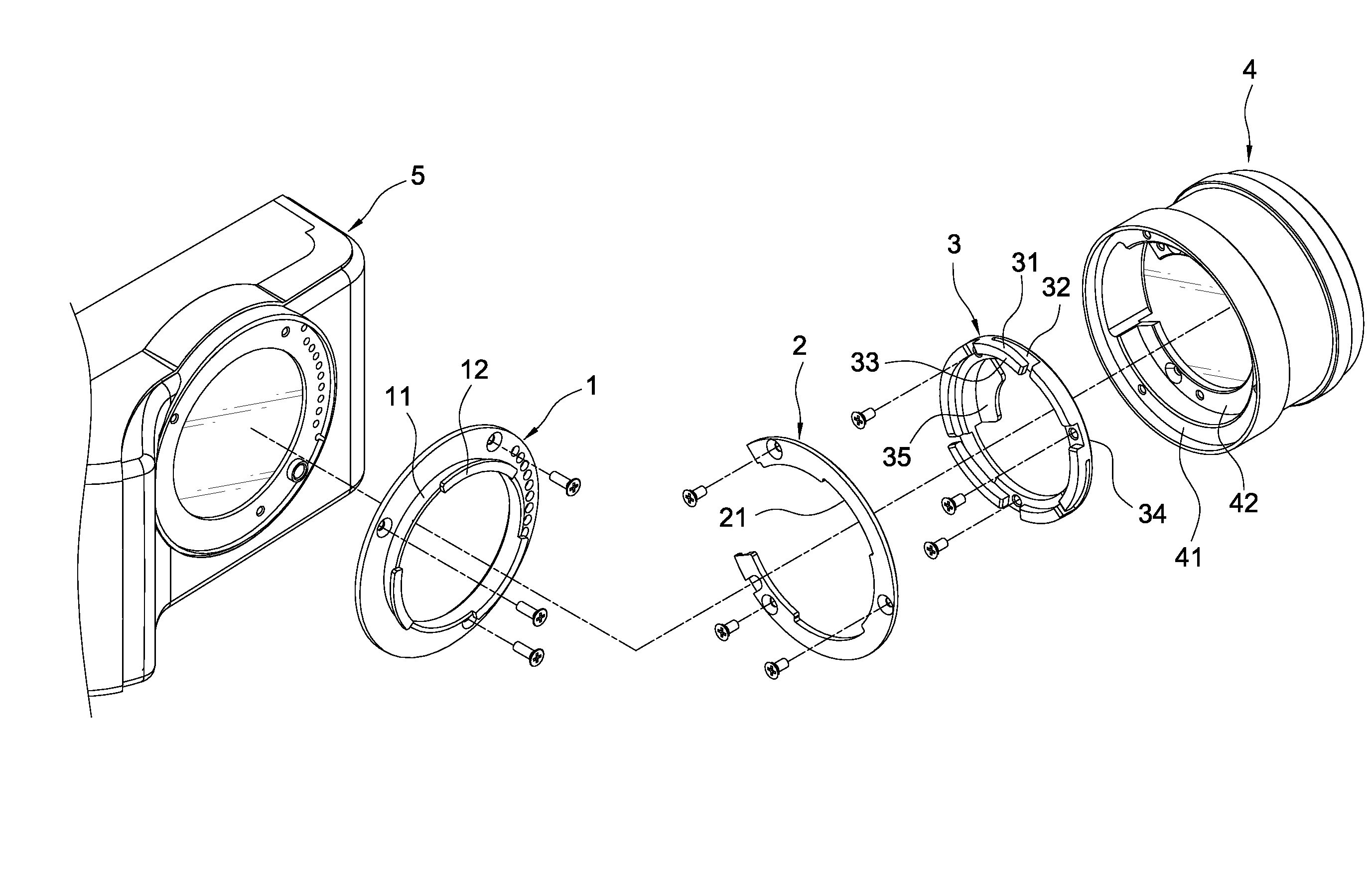
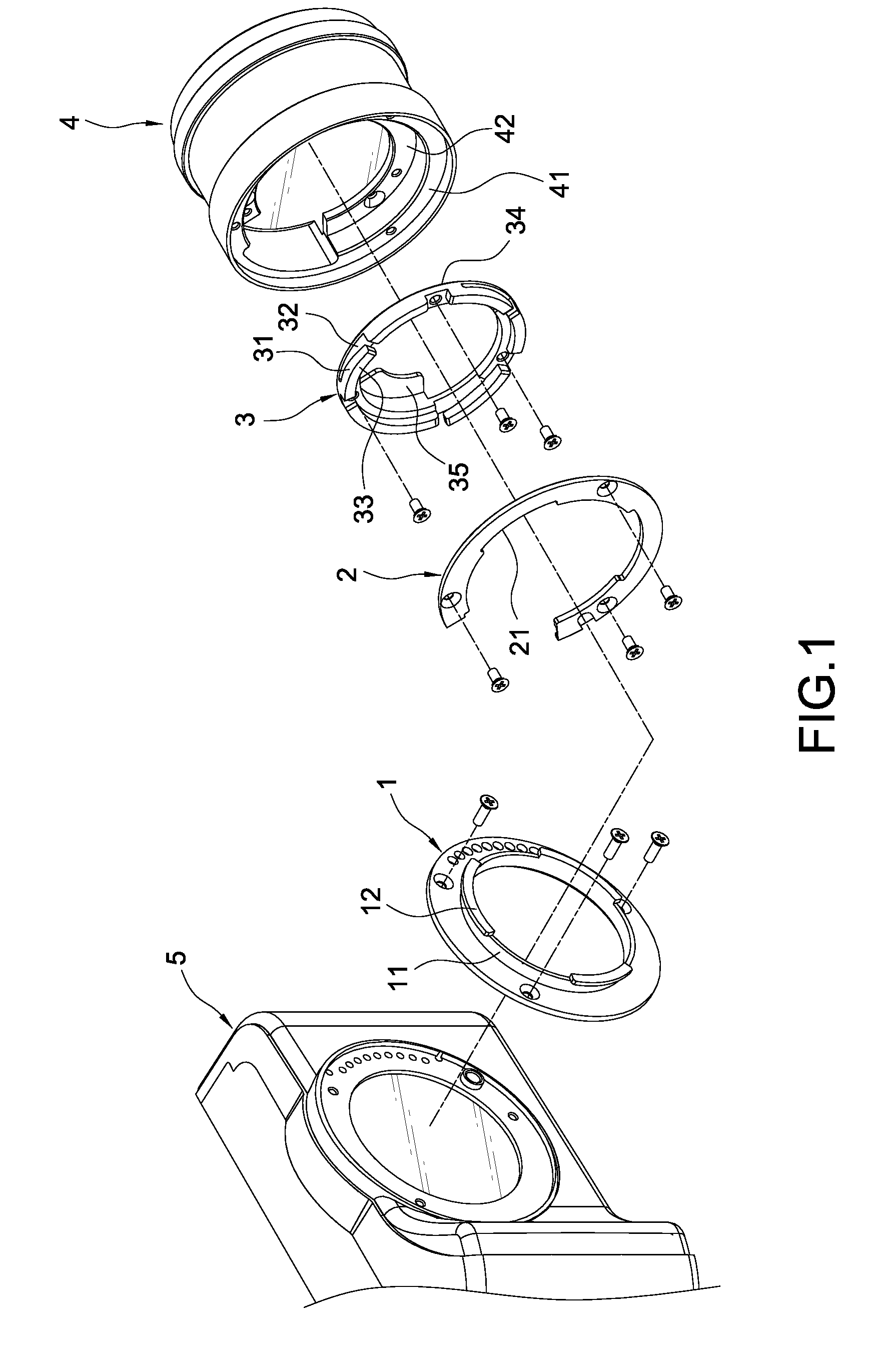
[0019]Please refer to FIG. 1, which is an exploded perspective view showing a preferred embodiment of the present invention. The present invention includes a base 1, a lens mount 2 and an abutting base 3. In the present embodiment, the base 1 and the abutting base are annular. The lens mount 2 is a C-shaped ring having an opening as shown in FIG. 1. The lens mount 2 also can be a closed ring. Those skilled in this art will understand that the shape is not limited thereto, but can be changed according to the desired object. The dimension of the base 1 is corresponding to that of the lens of a camera body 5. The inner edge of the base 1 protrudes outwardly to form an annular wall 11. The top end of the annular wall 11 further protrudes outwardly to form a plurality of curved blocks 12. The inner and outer diameters of the lens mount 2 are approximately identical to those of the base 1, while the thickness of the lens mount 2 is approximately identical to the height of the annular wall...


PUM


Abstract

A means for fixing an auxiliary lens to the outside of the original lens of a camera body includes an annular base, an annular lens mount and an annular abutting base. The inner edge of the base protrudes upwardly to form a wall. The wall protrudes outwards to form a plurality of blocks. The inner edge of the lens mount is provided with a plurality of notches corresponding to the blocks. A first end surface of the abutting base extends to form a plurality of L-shaped elastic arms corresponding to the blocks and notches. The L-shaped elastic arm extends obliquely from the first end surface toward the lens mount. A gap is formed between the L-shaped elastic arm and the abutting base, so that the L-shaped elastic arm can be bent inwardly when compressed. When the camera body is combined with the auxiliary lens by rotation, the blocks pass through the notches to abut and compress the L-shaped elastic arms. At the same time, the L-shaped elastic arms generate a reaction force, thereby enhancing the tightness between the camera body and the auxiliary lens.

Description

BACKGROUND OF THE INVENTION[0001]1. Field of the Invention[0002]The present invention relates to a camera, and in particular to an auxiliary lens for a compact camera.[0003]2. Description of Prior Art[0004]Since the camera has been invented, people like to use it to take a picture. Especially, when people are traveling, they always carry a camera with them. After a digital camera has been developed, it has been widely used because it features instant viewability and erasability.[0005]Like the traditional film cameras, the digital cameras can be classified into two categories, i.e. Single Lens Reflex cameras (SLR) and cameras. Since the compact cameras are highly portable, cheap in price and user-friendly, they are the mainstream in the market.[0006]However, the focal length of a fixed (un-interchangeable) lens equipped in a compact camera is approximately in the range of 35 to 105 mm, which is equivalent to the focal length of a 35 mm-type film camera. The minimum focus distance is ...

Claims


Application Information

Patent Timeline
Patent Type & Authority Patents(United States)
IPC IPC(8): G03B17/00H04N5/225G02B7/02G03B11/00
CPCG03B17/00
Inventor YANG, CHIH-YI
Owner LUMOS TECH
Why Eureka
Try Eureka