Systems and methods for a high-intensity light emitting diode floodlight

a light-emitting diode floodlight and high-intensity technology, applied in the direction of semiconductor devices for light sources, lighting and heating apparatus, lighting support devices, etc., can solve the problems of large electrical power consumption, inefficient lamps, and inability to meet the needs of lighting applications, so as to achieve the effect of dissipating hea

Active Publication Date: 2010-12-28
HONEYWELL INT INC
View PDF14 Cites 30 Cited by
  • Summary
  • Abstract
  • Description
  • Claims
  • Application Information

AI Technical Summary

Problems solved by technology

Some aerospace lighting applications require immense amounts of light to illuminate parts of the surrounding environment.
These lamps are fairly inefficient and require considerable quantities of electrical power to operate at the intended levels.
Most of this power is radiated as heat and creates extremely high temperatures.
Most importantly, halogen lights have a relatively short operating life and must be frequently replaced.
Though the lamps themselves are not excessively expensive, replacing lamps involves maintenance time, which costs aircraft owners a significant amount due to aircraft downtime and labor.
Though HID lamps have a longer operating life than their halogen counterparts, they have higher costs than a standard halogen lamp.
The HID systems also require warm-up time of several minutes and the lamps cannot be easily flashed or quickly started.
This limits the number of LEDs that can fit in a given size and complicates thermal management.

Method used


Image

  • Systems and methods for a high-intensity light emitting diode floodlight
  • Systems and methods for a high-intensity light emitting diode floodlight
  • Systems and methods for a high-intensity light emitting diode floodlight

Examples


Embodiment Construction

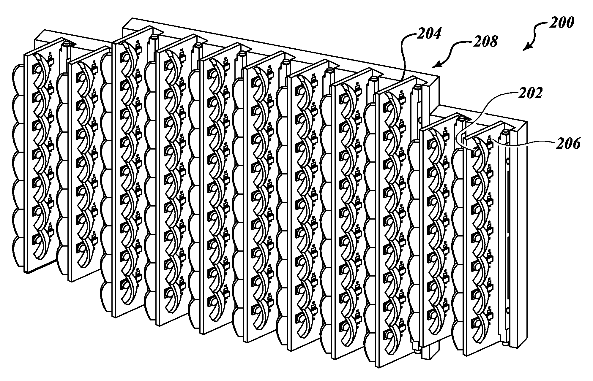
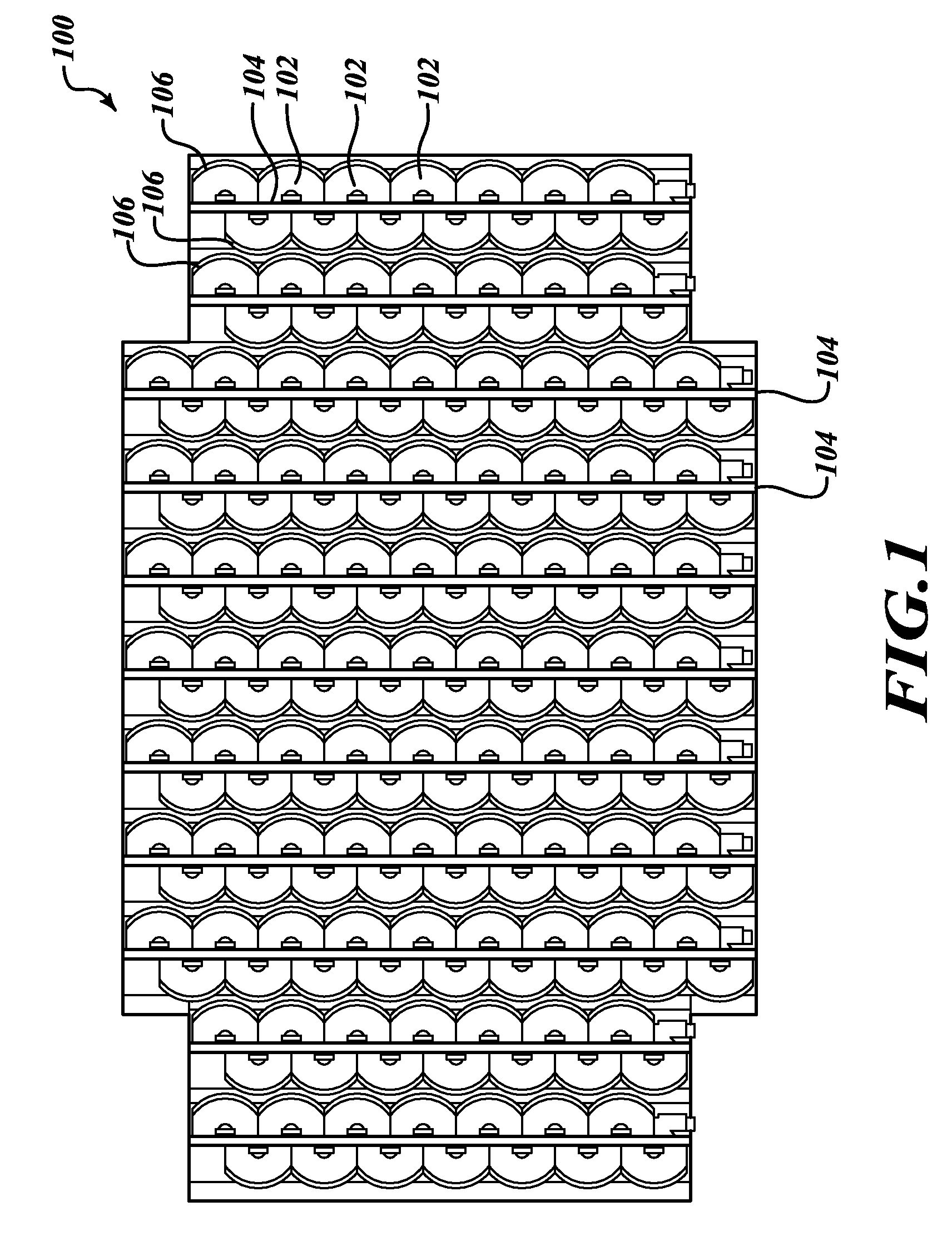
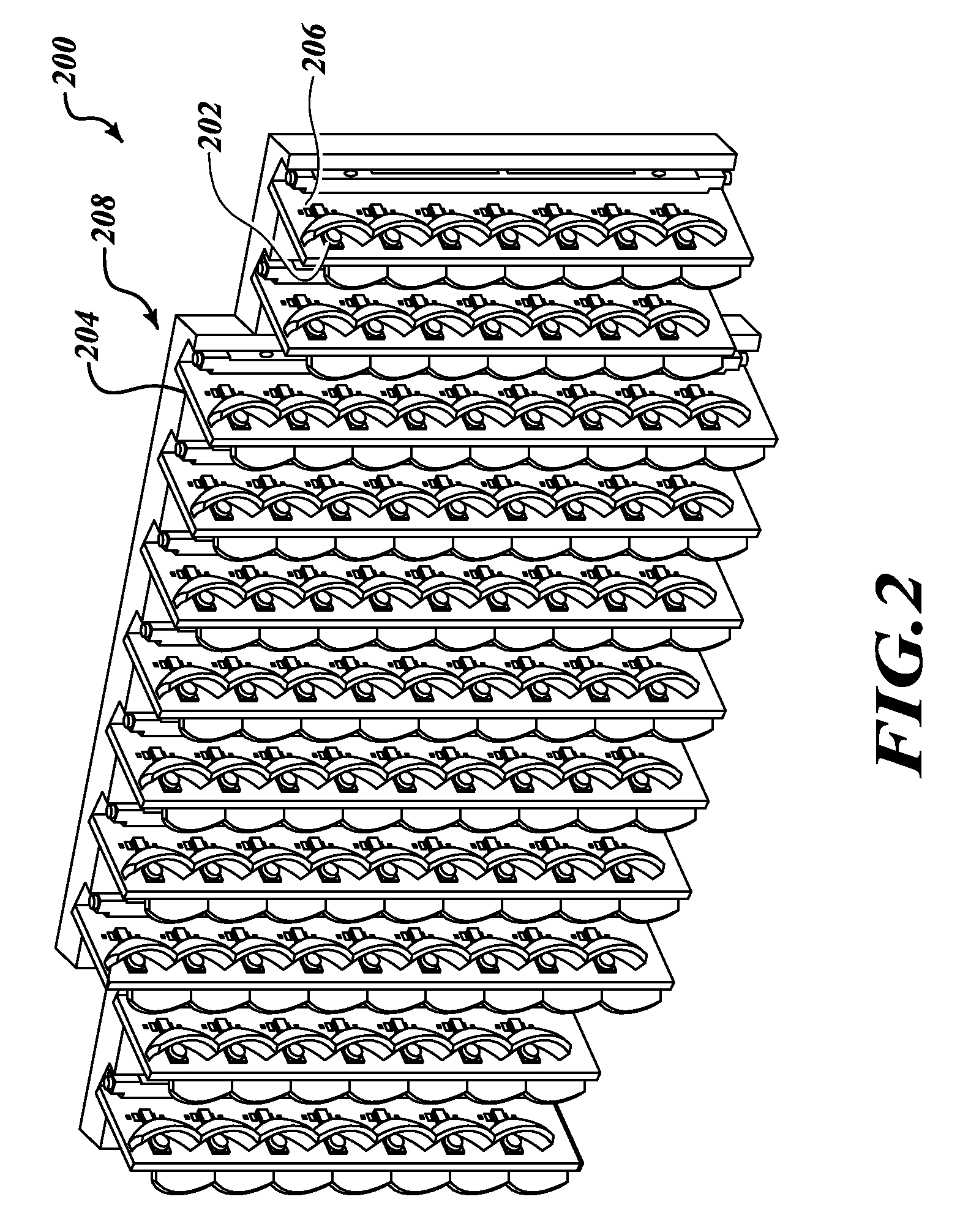
[0009]Systems and methods for a high-intensity light emitting diode (LED) floodlight are disclosed herein. In one embodiment, the floodlight utilizes a right-angle reflector design which allows a plurality of LEDs to be mounted in a perpendicular orientation to the designed light output. The orientation advantageously allows for more LEDs to be mounted than in a standard planar LED solution. The LEDs are mounted onto circuit cards (blades) which allow the LEDs to be activated and powered. In an alternate embodiment, the LEDs may be mounted directly onto a heat spreader. The circuit cards are mounted directly onto a heat spreader material with a high thermal conductivity, which functions as a heat sink fin. The heat sink fin advantageously reduces LED temperatures and therefore results in longer life and higher intensity. Once heat enters the fin, it is conducted through the fin to the heat sink and convected through the surrounding air such that the heat is preferably dissipated to ...


PUM


Abstract

Systems and methods for a high intensity light emitting diode (“LED”) floodlight. The floodlight has a designed direction of output and includes an LED; an optical element; a blade; and a heat sink. The blade is mounted at an application-specific angle to the heat sink to obtain the designed direction of output. The blade has an LED and an optical element; and a fixed end coupled with the heat sink. The heat sink is configured to dissipate heat away from the LED on the blade. The blade is configured to activate the LED and using the optical element, redirect the light in the direction of the designed output of the floodlight.

Description

BACKGROUND OF THE INVENTION[0001]Some aerospace lighting applications require immense amounts of light to illuminate parts of the surrounding environment. A traditional lighting solution uses a large halogen lamp with an internal parabolic reflector. These lamps are fairly inefficient and require considerable quantities of electrical power to operate at the intended levels. Most of this power is radiated as heat and creates extremely high temperatures. These lamps must be isolated from other aircraft components so the heat does not interfere with other systems or injure maintenance personnel. Most importantly, halogen lights have a relatively short operating life and must be frequently replaced. Though the lamps themselves are not excessively expensive, replacing lamps involves maintenance time, which costs aircraft owners a significant amount due to aircraft downtime and labor.[0002]A more recent solution for aerospace lighting utilizes High-Intensity Discharge (“HID”) systems. Tho...

Claims


Application Information

Patent Timeline
Patent Type & Authority Patents(United States)
IPC IPC(8): F21V7/00F21V29/00
CPCF21K9/00F21V29/004F21V29/85F21V29/70B64D47/04B64D2203/00F21S2/005F21Y2101/02F21Y2105/001Y10S362/80F21W2101/06F21Y2105/10F21Y2115/10F21W2107/30
Inventor STORCH, DAVID ROBERTSINGER, JEFFREY M.BARNETT, DAVID
Owner HONEYWELL INT INC
Why Eureka
Try Eureka