Subsurface rendering methods and apparatus

a surface rendering and subsurface technology, applied in the field of computer animation, can solve the problems of not addressing the fundamental problem, the surface based approach suffers from technical difficulties in the parametric representation of sample locations, and the approach is generally very time-consuming, and achieves smoothness across multiple geometry elements

Inactive Publication Date: 2010-12-28
PIXAR ANIMATION
View PDF43 Cites 4 Cited by
  • Summary
  • Abstract
  • Description
  • Claims
  • Application Information

AI Technical Summary

Benefits of technology

[0014]The techniques described below are based on an explicit representation of the subsurface illumination fluxes on a 3 dimensional grid. This representation allows the efficient spatial indexing of illumination samples from the unstructured geometry of the object. This representation allows the rendering engine to quickly solve the transport of diffuse illumination inside the translucent material with full representation of the internal structure.
[0015]The process described below includes the following phases: 1) evaluation of surface illumination on object, collection of surface illumination (diffuse reflection), determining of area weighting, and scattering properties on sample grids; 2) efficient determination of the diffuse radiative transfer on the sample grids; and 3) sampling the diffuse illumination during final rendering pass.
[0018]The third phase of the process is to take the completed grid containing the solved diffuse illumination compensation values and point sample the grid using an interpolation kernel from the surface shaders. This may occur during a final rendering pass for the surface. All of the sample processing for this phase is done in global 3-space so that no surface coordinate parameterizations are needed and smoothness across multiple geometry elements is provided.

Problems solved by technology

Surface based approaches suffer from technical difficulties in the parametric representation of sample locations.
Additionally, such approaches do not address the fundamental problem of representing an internal structure of the scattering media.
Stochastic ray tracing approaches can be used to solve the full physical problem, however such approaches are generally very time consuming.
Again such approaches are very computationally intensive.
Because the present solutions to the problem of rendering objects of translucent materials is slow, animators using such rendering techniques cannot quickly see how the animation will look.

Method used


Image

  • Subsurface rendering methods and apparatus
  • Subsurface rendering methods and apparatus
  • Subsurface rendering methods and apparatus

Examples


Embodiment Construction

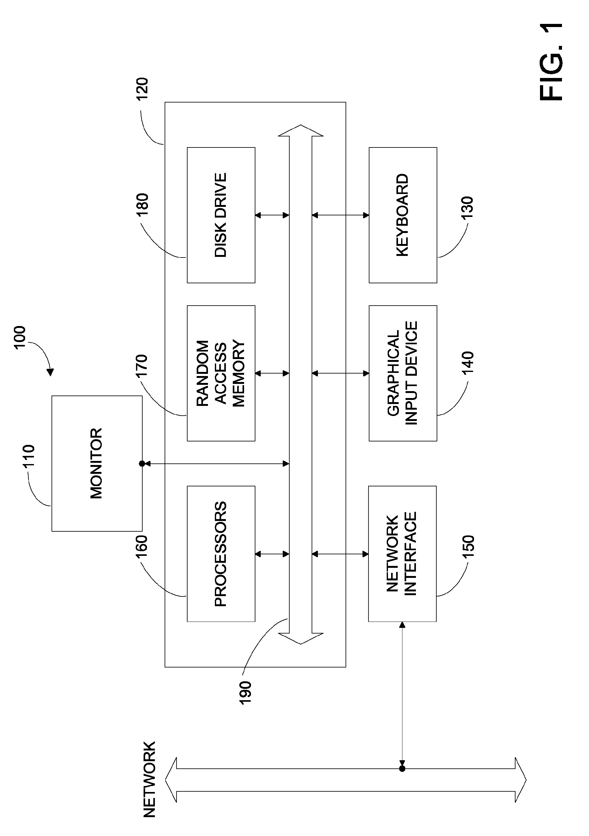
[0038]FIG. 1 is a block diagram of typical computer system 100 according to an embodiment of the present invention.

[0039]In the present embodiment, computer system 100 typically includes a monitor 110, computer 120, a keyboard 130, a user input device 140, a network interface 150, and the like.

[0040]In the present embodiment, user input device 140 is typically embodied as a computer mouse, a trackball, a track pad, wireless remote, and the like. User input device 140 typically allows a user to select objects, icons, text and the like that appear on the monitor 110.

[0041]Embodiments of network interface 150 typically include an Ethernet card, a modem (telephone, satellite, cable, ISDN), (asynchronous) digital subscriber line (DSL) unit, and the like. Network interface 150 are typically coupled to a computer network as shown. In other embodiments, network interface 150 may be physically integrated on the motherboard of computer 120, may be a software program, such as soft DSL, or the ...


PUM


Abstract

A method for a computer system includes receiving a three-dimensional model of an object, wherein the object includes a surface region, determining an incident irradiance associated with the surface region, determining a plurality of voxels associated with the three-dimensional model of the object, wherein a first plurality of voxels is associated with the surface region, and wherein a second plurality of voxels is associated with a sub-surface region of the object, associating the incident irradiance with the second plurality of voxels, and determining a subsurface scattering contribution associated with the surface region of the object in response to the incident irradiance associated with the second plurality of voxels.

Description

CROSS-REFERENCES TO RELATED APPLICATIONS[0001]The present application claims priority to and is a non-provisional application of U.S. Provisional Patent Ser. No. 61 / 060,026 filed Jun. 9, 2008. This application is also a continuation-in-part of 11 / 084,697, filed Mar. 18, 2005, now allowed. This case is also related to application Ser. No. 12 / 259,062, filed Oct. 27, 2008, titled “Translucent Object Rendering Methods and Apparatus. These disclosures are hereby incorporated by reference in their entirety for all purposes.BACKGROUND OF THE INVENTION[0002]The present invention relates to computer animation. More particularly, the present invention relates to techniques and apparatus for efficient rendering of objects that are specified to include translucent materials.[0003]Throughout the years, movie makers have often tried to tell stories involving make-believe creatures, far away places, and fantastic things. To do so, they have often relied on animation techniques to bring the make-be...

Claims


Application Information

Patent Timeline
Patent Type & Authority Patents(United States)
IPC IPC(8): G06T17/00
CPCG06T15/506
Inventor TOMSON, ERINPLANCK, MAXWELLANDERSON, JOHN R.
Owner PIXAR ANIMATION
Why Eureka
Try Eureka