Compliant pin for retaining and electrically connecting a shield with a connector assembly

a technology of shields and connector assemblies, applied in the direction of coupling devices, coupling contact members, two-part coupling devices, etc., can solve the problems of eon pins buckling, eon pins requiring relatively large insertion forces

Active Publication Date: 2011-01-04
TYCO ELECTRONICS LOGISTICS AG (CH)
View PDF18 Cites 28 Cited by
  • Summary
  • Abstract
  • Description
  • Claims
  • Application Information

AI Technical Summary

Problems solved by technology

Moreover, these EON pins require relatively large insertion forces when compared to the structural integrity of the EON pins.
For example, the insertion forces required to press-fit the EON pins into the cavities frequently cause the EON pins to buckle if the EON pins are not perfectly aligned with the cavities.

Method used


Image

  • Compliant pin for retaining and electrically connecting a shield with a connector assembly
  • Compliant pin for retaining and electrically connecting a shield with a connector assembly
  • Compliant pin for retaining and electrically connecting a shield with a connector assembly

Examples


Embodiment Construction

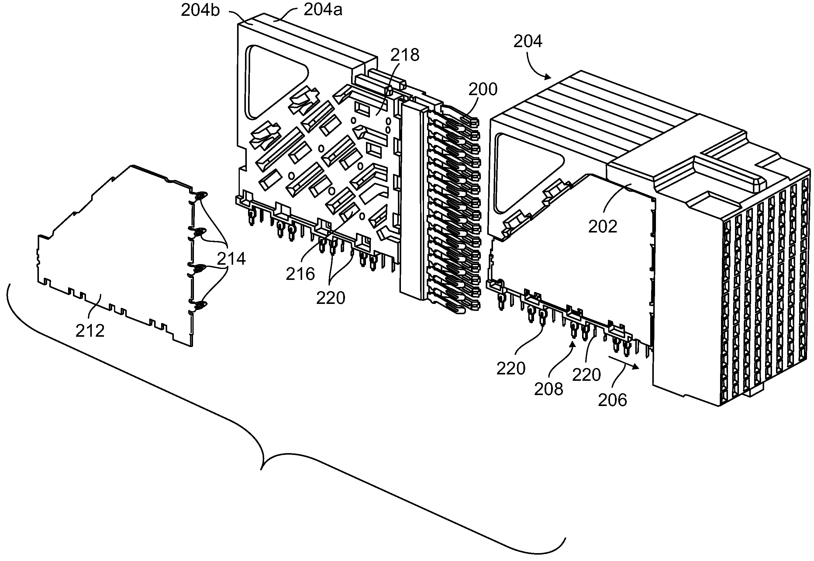
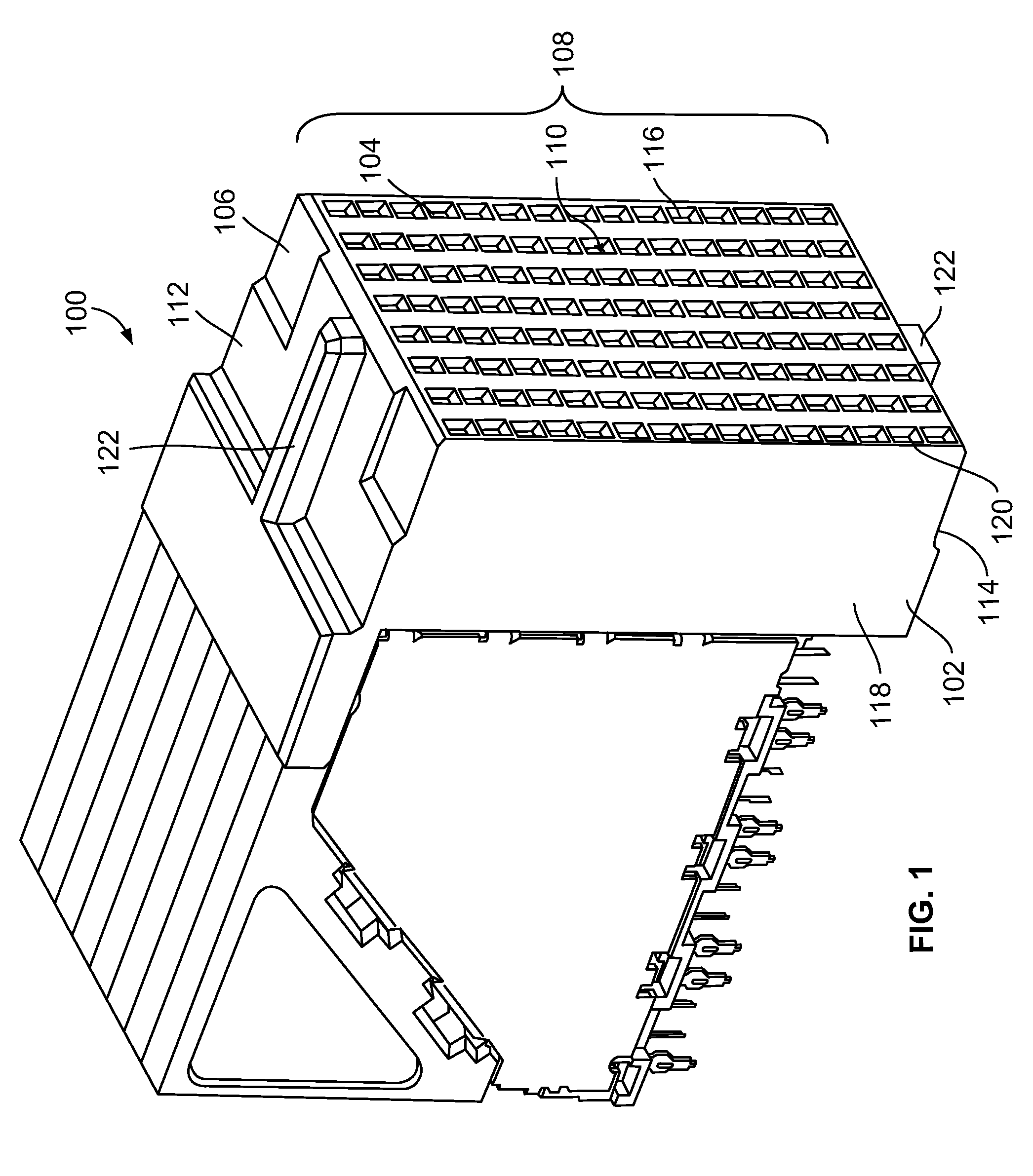
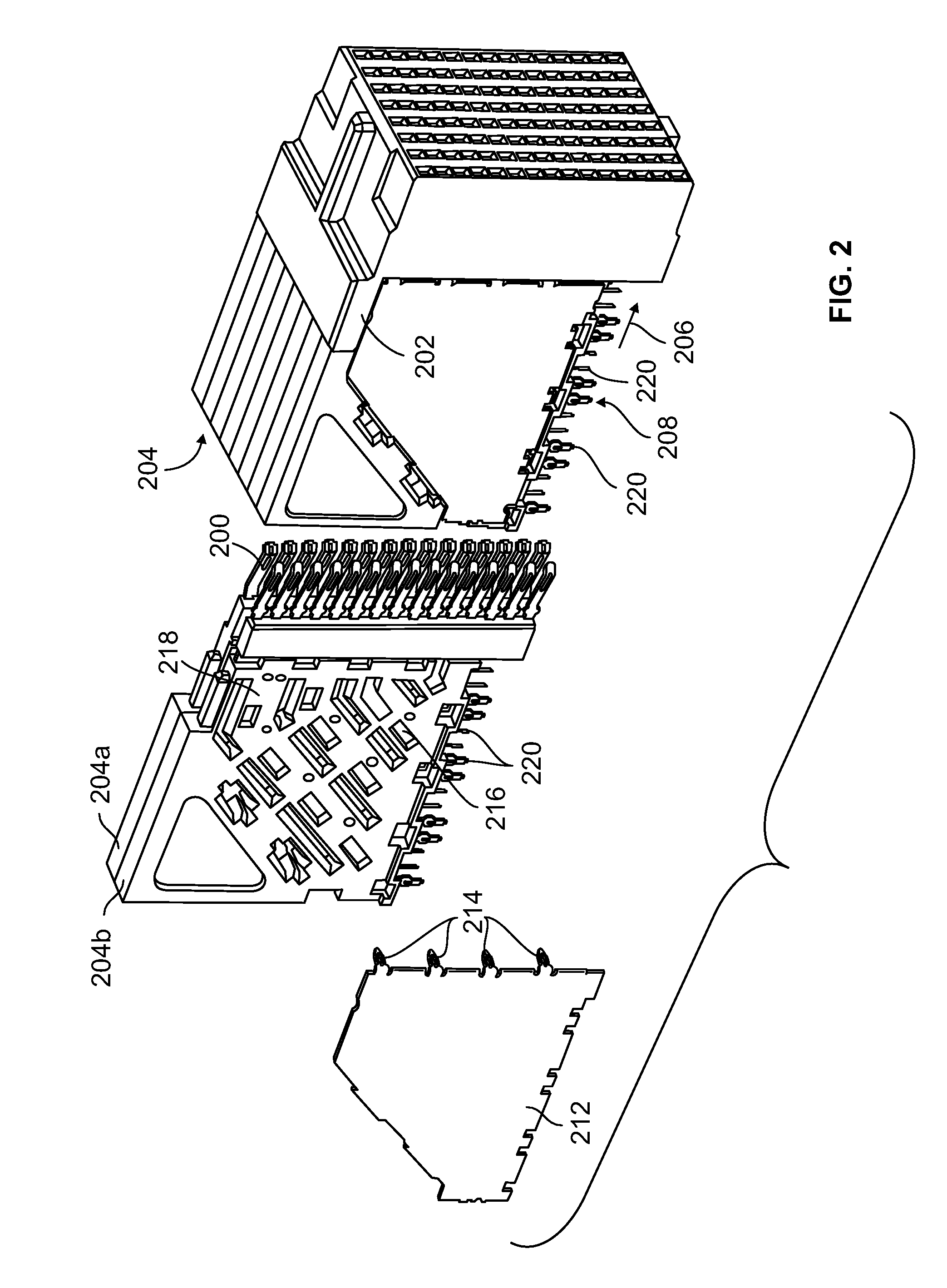
[0014]FIG. 1 is a perspective view of an electrical connector assembly 100 according to one embodiment. While the connector assembly 100 is described herein with particular reference to a backplane receptacle connector, it is to be understood that the benefits herein described are also applicable to other connectors in alternative embodiments. The following description is therefore provided for purposes of illustration, rather than limitation, and is but one potential application of the subject matter herein. The connector assembly 100 includes a dielectric housing 102 having a forward mating end 104 that includes a shroud 106 having a mating interface 108 at the mating end 104. A plurality of mating contacts 200 (shown in FIG. 2), such as, for example, contacts within contact cavities 110, are provided proximate to the mating interface 108 and are configured to receive corresponding mating contacts (not shown) from a mating connector (not shown). The shroud 106 includes an upper su...


PUM


Abstract

A compliant pin is configured to be press-fit into a cavity of at least one of a connector assembly and a substrate to retain the pin in the cavity. The pin includes a neck, a plurality of compliant beams, and an insertion tip. The neck interconnects the pin with the connector assembly. The beams are configured to engage an inner surface of the cavity to retain the pin in the cavity. The beams are arranged side-to-side and project along a longitudinal plane in a loading direction. The beams have arcuate portions that are arched in different directions transverse to the longitudinal plane. The arcuate portions are shaped to deflect toward the longitudinal plane without substantially engaging one another. The insertion tip interconnects the ends of the beams.

Description

BACKGROUND OF THE INVENTION[0001]The subject matter herein generally relates to electrical connectors and, more particularly, to compliant pins for electrical connectors.[0002]Known Eye-Of-Needle (“EON”) pins are used to mechanically and electrically connect shields in connector assemblies with at least one of another component of the connector assembly and a substrate. For example, known EON pins are used to electrically connect shields with the electric ground of a circuit board and / or a conductor that is electrically connected to the electric ground of the circuit board. The EON pins are press-fit into cavities in the circuit board and / or another component in the connector assembly. The EON pins include an approximately oval shaped opening enclosed by outwardly bent beams of the EON pins. The EON pins are press-fit into cavities by applying an insertion force on the EON pins in a loading direction directed into the cavities. Application of the insertion force on the EON pins in t...

Claims


Application Information

Patent Timeline
Patent Type & Authority Patents(United States)
IPC IPC(8): H01R13/648
CPCH01R12/585H01R23/688H01R13/6587
Inventor SYPOLT, MATTHEWFEDDER, JAMES LEE
Owner TYCO ELECTRONICS LOGISTICS AG (CH)
Why Eureka
Try Eureka