Method and apparatus for the conditioning and homogenization of glass melts

a technology of glass melt and homogenization, which is applied in the field of conditioning and homogenizing glass melt, can solve the problems of large glass loss, long cleaning period, and differences in glass concentration and density, and achieve the effect of effective homogenizing the main glass flow, reducing cleaning time and glass loss, and high flexibility of the total plan

Inactive Publication Date: 2007-04-26
BETEILIGUNGEN SORG
View PDF6 Cites 22 Cited by
  • Summary
  • Abstract
  • Description
  • Claims
  • Application Information

AI Technical Summary

Benefits of technology

[0026] On the one hand, the invention achieves effective homogenization of the main glass flow in the channel and on the other hand, achieves a high flexibility of the total plant. As a result, when the change from one glass type to the next is made, cleaning times and glass losses are reduced. In particular, with the coloring processes fewer coloring agents must be added and when the change is made to different coloring agents, shorter cleaning and shutdown times and fewer glass losses are the result.
[0033] the glass level near the stirrers is between 140 and 230 mm.
[0034] The invention also concerns an apparatus for conditioning and homogenizing glass melts with at least one flow channel with a vertical central longitudin

Problems solved by technology

This results in differences in the concentration and the density in the glass.
However, as on the one hand very long residence times are required for these processes, and on the other hand the complete bulk of the glass is not involved in equal measure, an attempt is made to speed up these processes by means of intensive forced mixing.
This results in long cleaning periods and a great loss of glass when the self-cleaning method is used after a glass change.
The disadvantages of these concepts lie in their limited mixing capacity.
On the other hand, it also has the disadvantage that the channel bottom is not flat.
This in turn means that longer cleaning periods and high colorant and glass losses must be expected on such installations.
However, despite the complicated multi-level installation the mixing effect is limit

Method used


Image

  • Method and apparatus for the conditioning and homogenization of glass melts
  • Method and apparatus for the conditioning and homogenization of glass melts
  • Method and apparatus for the conditioning and homogenization of glass melts

Examples


Embodiment Construction

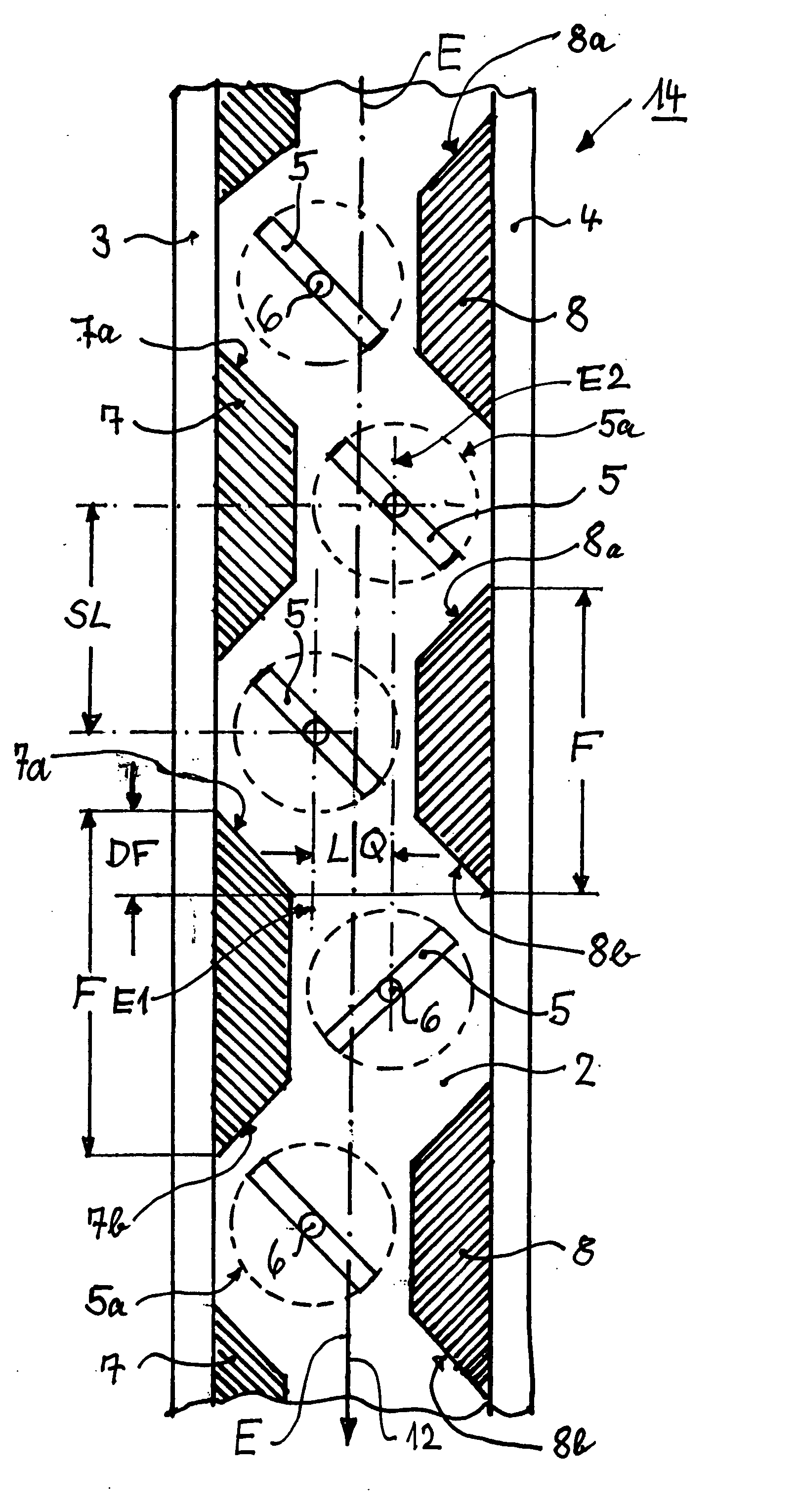
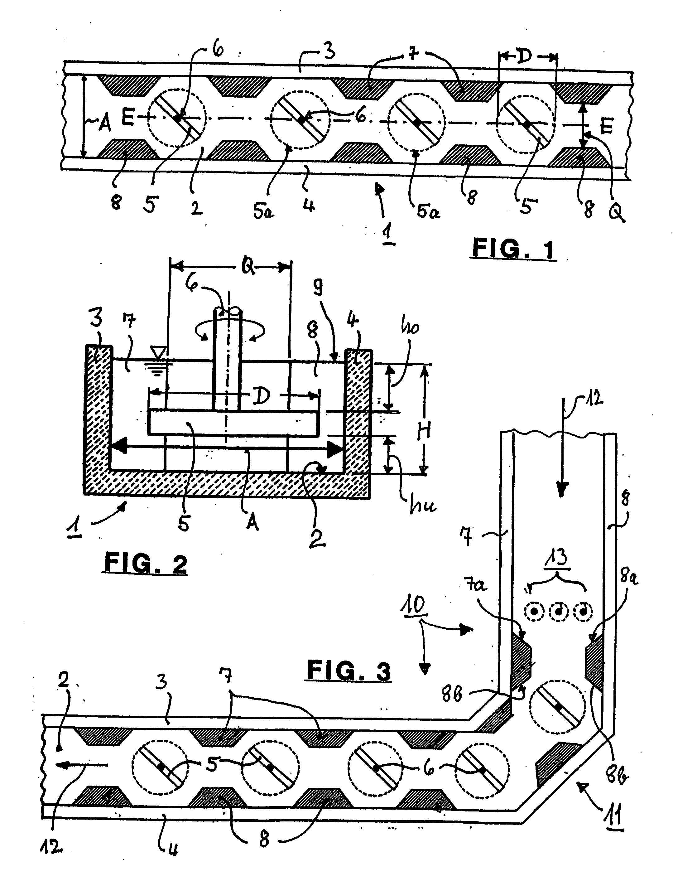
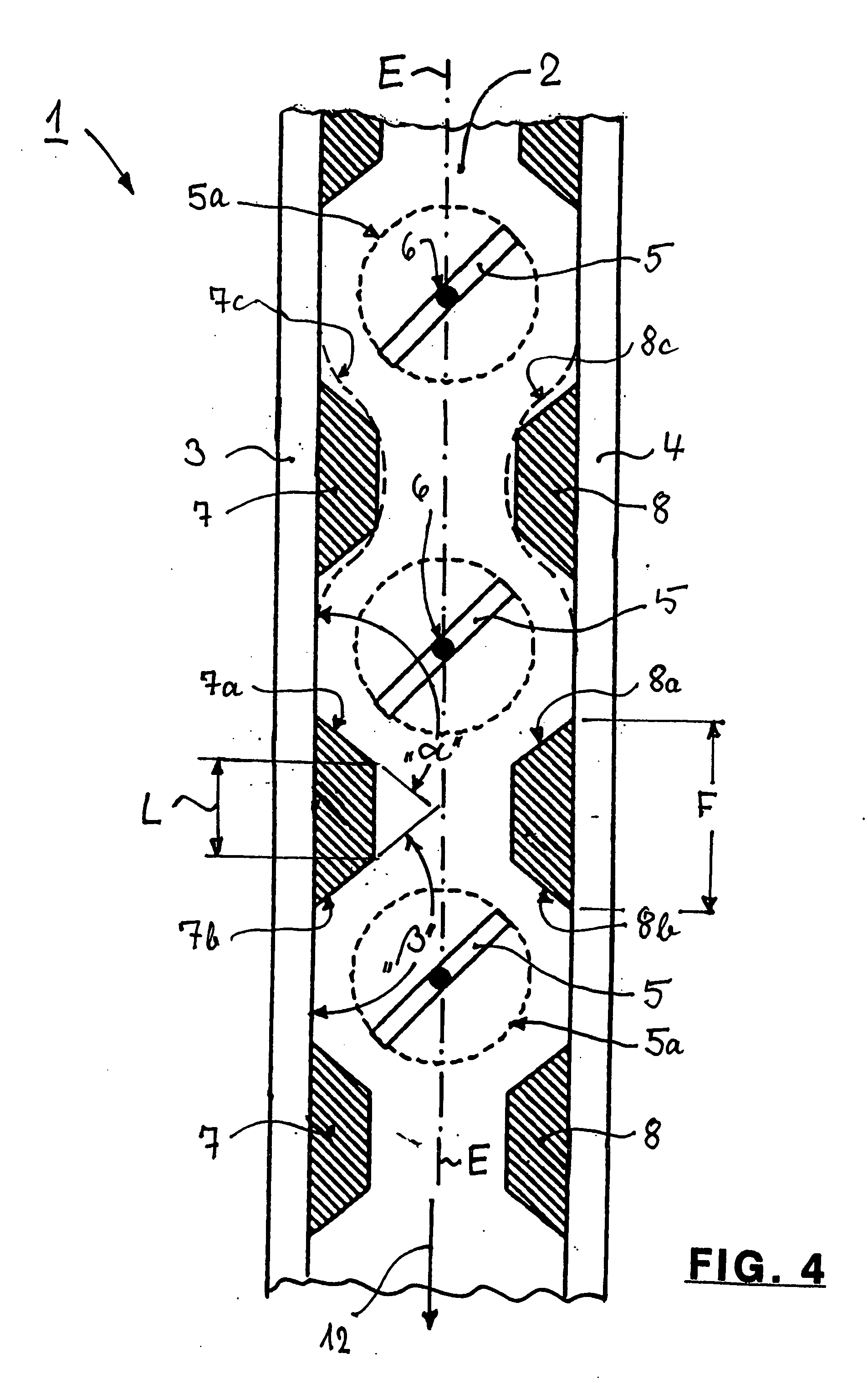
[0062]FIG. 1 shows a flow channel 1 with a flat channel bottom 2, two vertical parallel side walls 3 and 4 and four stirrers 5 with vertical stirrer shafts 6. The broken circles represent the so-called enveloping surfaces 5a that are traversed by the outermost points of the stirrer paddles during rotation of the stirrers 5. The diameter “D” of these circles and so also of the stirrer paddles, is between 360 and 560 mm. The inner channel width is defined by the clearance “A”, which is at least 400 mm and may even exceed 1000 mm, and so determines the width of the glass flow.

[0063] The flow channel 1 has a vertical central longitudinal plane E-E, in which the axes of the stirrer shafts 6 lie. The side walls 3 and 4 have protrusions 7 and 8, that are installed opposite to one another in pairs and symmetrical to the central longitudinal plane E-E, and reduce the clearance “A” of the cross-section to dimension “Q”. The ratio Q:A is between 0.5 and 0.9. This produces so-called pockets, i...


PUM

PropertyMeasurementUnit
Lengthaaaaaaaaaa
Lengthaaaaaaaaaa
Lengthaaaaaaaaaa

Abstract

A method and apparatus for the conditioning and homogenization of glass melts that are transported in flow channels with a vertical central longitudinal plane and side walls, by using the effect of alternating cross-section changes in the flow direction and stirrers with vertical stirrer shafts installed in the flow direction. The glass melt is transported through at least one flow channel, in which cross-section changes on both sides are created by several consecutive protrusions installed in the flow direction. The protrusions are directed towards the central longitudinal plane and on their upstream sides and downstream sides have wall areas that are arranged at such an angle to the central longitudinal plane, that no right-angled or acute-angled corners are created in the flow channel. The stirrers are installed between consecutive downstream sides and the upstream sides of the protrusions.

Description

BACKGROUND OF THE INVENTION [0001] The invention concerns a method for conditioning and homogenization of glass melts that flow in flow channels with a vertical central longitudinal plane and side walls, using the effect of alternating cross-section changes and stirrers with vertical stirrer shafts, installed in the flow direction. The Problems that Occur During the Homogenization of Glass: [0002] A glass with certain transmission properties is produced by the addition of concentrates that influence the transmission, such concentrates being preferably added to a flint or light base glass in a forehearth or flow channel filled with glass. The concentrates, being carriers of components such as polyvalent ions that influence the transmission, are added and must first be melted. This results in differences in the concentration and the density in the glass. These must be equalized to the extent that no differences in concentration or transmission can be determined in the end product. Di...

Claims


Application Information

Patent Timeline
IPC IPC(8): C03B5/18C03B5/16
CPCB01F5/0646B01F5/0655B01F7/00908B01F7/00975B01F7/1665C03B5/173C03B5/182C03B5/187C03B7/02B01F25/4338B01F25/433B01F27/50B01F27/2322B01F27/85
Inventor LINDIG, MATTHIASGESSLEIN, JOACHIM
Owner BETEILIGUNGEN SORG
Why Eureka
Try Eureka