Fuel vapor processing apparatus

a technology of a processing apparatus and a fuel vapor, which is applied in the direction of machines/engines, non-fuel substance addition to fuel, and charge feed systems, etc., can solve the problems of reducing the adsorption capacity and the fuel vapor is not uniform, and achieves efficient homogenization of purge air, easy mixing, and convenient mixing

Active Publication Date: 2021-11-30
AISAN IND CO LTD
View PDF15 Cites 0 Cited by
  • Summary
  • Abstract
  • Description
  • Claims
  • Application Information

AI Technical Summary

Benefits of technology

[0011]According to this aspect, while the gas flows through the agitation chamber, the gas is spirally guided and stirred by the spiral flow forming part of the mixer in the agitation chamber. Thus, during the purge operation, the purge air is easily mixed in the agitation chamber so as to efficiently homogenize the purge air. The desorption efficiency of the fuel vapor in the purge port-side adsorption chamber by introducing the homogenized purge air into the purge port-side adsorption chamber. Similarly, during the adsorption operation, the fuel vapor-containing gas is easily mixed in the agitation chamber so as to efficiently homogenize the fuel vapor-containing gas. The adsorption efficiency of the fuel vapor in the atmospheric port-side adsorption chamber is increased by introducing the homogenized fuel vapor-containing gas into the atmospheric port-side adsorption chamber.

Problems solved by technology

Thus, the fuel vapor is not uniformly purged from the adsorbent such that the fuel vapor tends to remain in the outer peripheral portion of the adsorption chamber.
More specifically, the higher the temperature of the adsorbent, the lower the adsorption capacity thereof.

Method used


Image

  • Fuel vapor processing apparatus
  • Fuel vapor processing apparatus
  • Fuel vapor processing apparatus

Examples


first embodiment

[0062]Next, other embodiments will be described with reference to the accompanying drawings. In general, the additional embodiments described below are substantially the same as the first embodiment described above with some changes to the shape of the first mixer. Thus, while the changes will be described, same configurations will not be described in the interest of conciseness.

second embodiment

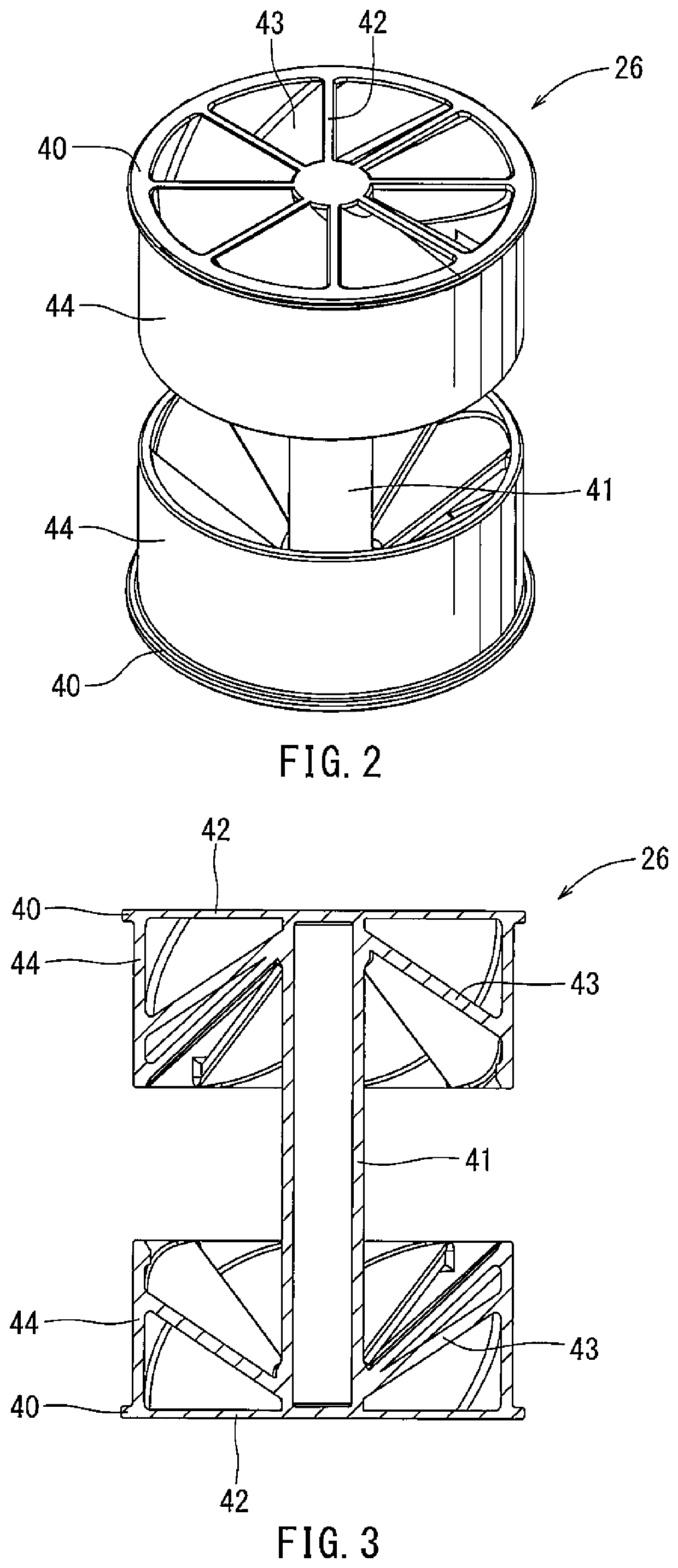
[0063]As shown in FIG. 6, a first mixer 60 includes a fitting part 62, a shaft part 64, connection parts 66, and agitation blades 68. The fitting part 62, the shaft part 64, the connection parts 66, and the agitation blades 68 of the first mixer 60 have the same configurations as the fitting part 40, the shaft part 41, the connection parts 42, and the agitation blades 43, respectively, as previously described. That is, as shown in FIGS. 2 and 6, the first mixer 60 differs from the first mixer 26 in that the first mixer 60 includes no outer wall (e.g., outer circumferential wall 44).

third embodiment

[0064]As shown in FIG. 7, an upper half of a first mixer 70 includes a fitting part 72, a shaft part 74, connection parts 76, and agitation blades 78. The fitting part 72, the shaft part 74, the connection parts 76, and the agitation blades 78 of the upper half of the first mixer 70 have the same configurations as the fitting part 62, the shaft part 64, the connection parts 66, and the agitation blades 68, respectively, of the upper half of the first mixer 60 previously described. On the other hand, a lower half of the first mixer 70 includes the fitting part 72, the shaft part 74, and the connection parts 76 only. That is, as shown in FIGS. 6 and 7, the first mixer 70 differs from the first mixer 60 in that the lower half of the first mixer 70 does not include any agitation blade (e.g., agitation blades 43). The first mixer 70 is disposed in the agitation chamber 36 such that the upper half including the agitation blades 78 is adjacent to the third adsorption chamber 35. That is, t...


PUM


Abstract

A fuel vapor processing apparatus includes a casing, an adsorbent, and a mixer. The casing includes an atmospheric port and a purge port. In addition, the casing forms an atmospheric port-side adsorption chamber, an agitation chamber, and a purge port-side adsorption chamber therein. The atmospheric port-side adsorption chamber, the agitation chamber, and the purge port-side adsorption chamber are continuously arranged in a gas flow direction from the atmospheric port through the casing to the purge port. The adsorbent fills the atmospheric port-side adsorption chamber and the purge port-side adsorption chamber. The adsorbent is configured to adsorb and desorb fuel vapor. The mixer is disposed in the agitation chamber and includes a spiral flow forming part configured to spirally guide gas flowing through the agitation chamber.

Description

CROSS-REFERENCE TO RELATED APPLICATIONS[0001]This application claims priority to Japanese patent application serial number 2018-128218, filed Jul. 5, 2018 which is hereby incorporated herein by reference in its entirety for all purposes.STATEMENT REGARDING FEDERALLY SPONSORED RESEARCH OR DEVELOPMENT[0002]Not applicable.BACKGROUND[0003]This disclosure relates generally to fuel vapor processing apparatuses.[0004]A vehicle, such as an automobile, is equipped with a fuel vapor processing apparatus. The fuel vapor processing apparatus has an adsorption chamber filled with an adsorbent capable of adsorbing and desorbing fuel vapor so as to prevent leakage of the fuel vapor from a fuel tank into the atmosphere. Such fuel vapor processing apparatus is also referred to as a canister. During parking or the like, when the fuel vapor generates in the fuel tank and flows into the adsorption chamber of the fuel vapor processing apparatus, the adsorbent in the adsorption chamber adsorbs the fuel v...

Claims


Application Information

Patent Timeline
Patent Type & Authority Patents(United States)
IPC IPC(8): F02M25/08
CPCF02M25/0854F02M25/08F02M25/089
Inventor MURATA, KAZUHOYAMAUCHI, TOSHIHIKO
Owner AISAN IND CO LTD
Why Eureka
Try Eureka