Pilot switch

a pilot switch and switch technology, applied in circuit-breaking switches, circuit-breaking switches for excess currents, relays, etc., can solve the problems of parasitic capacitance, fet switches may alter rf signals, fet switches may generate higher insertion loss than is generated, etc., to reduce or eliminate arcing

Active Publication Date: 2011-01-04
QORVO US INC
View PDF10 Cites 46 Cited by
  • Summary
  • Abstract
  • Description
  • Claims
  • Application Information

AI Technical Summary

Benefits of technology

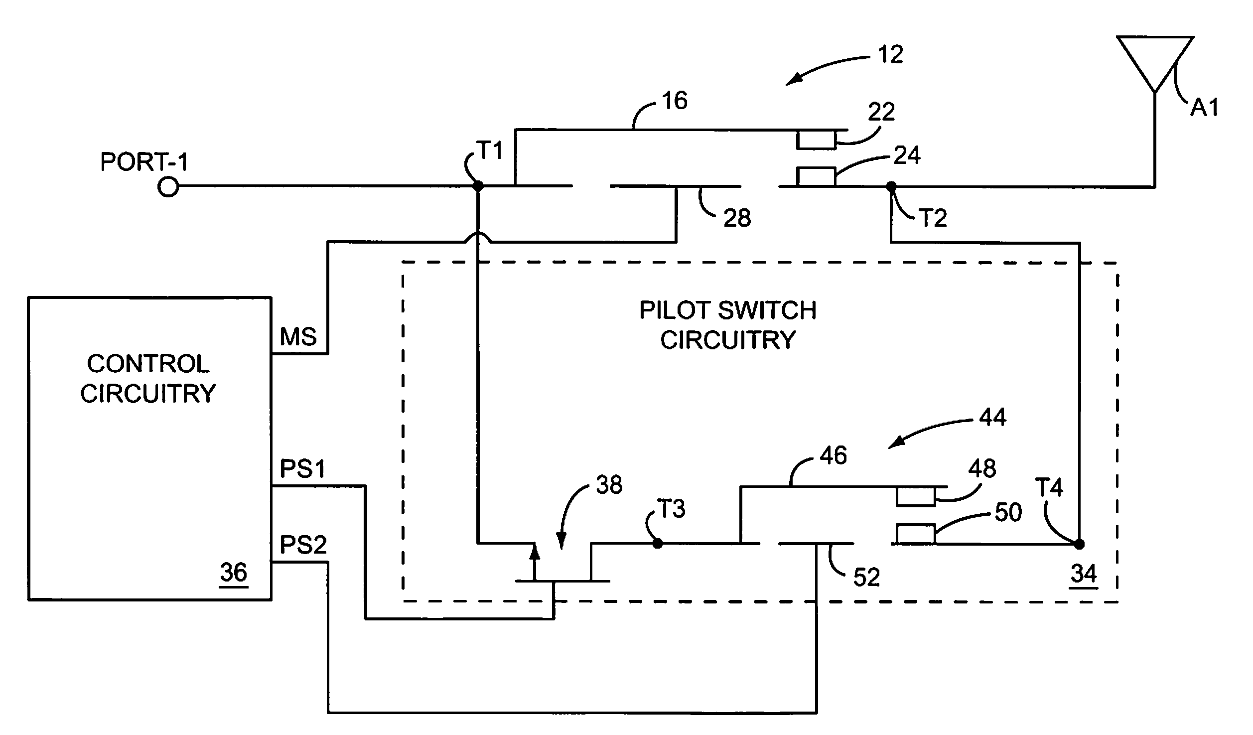
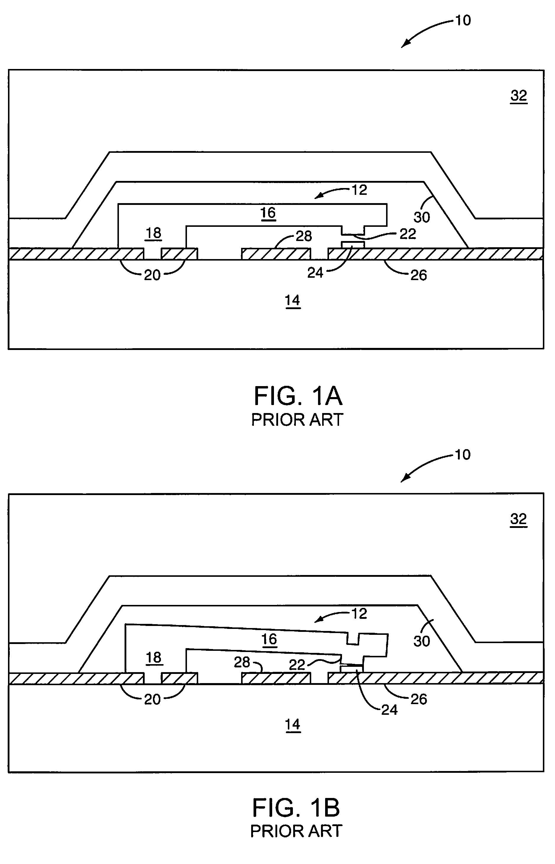
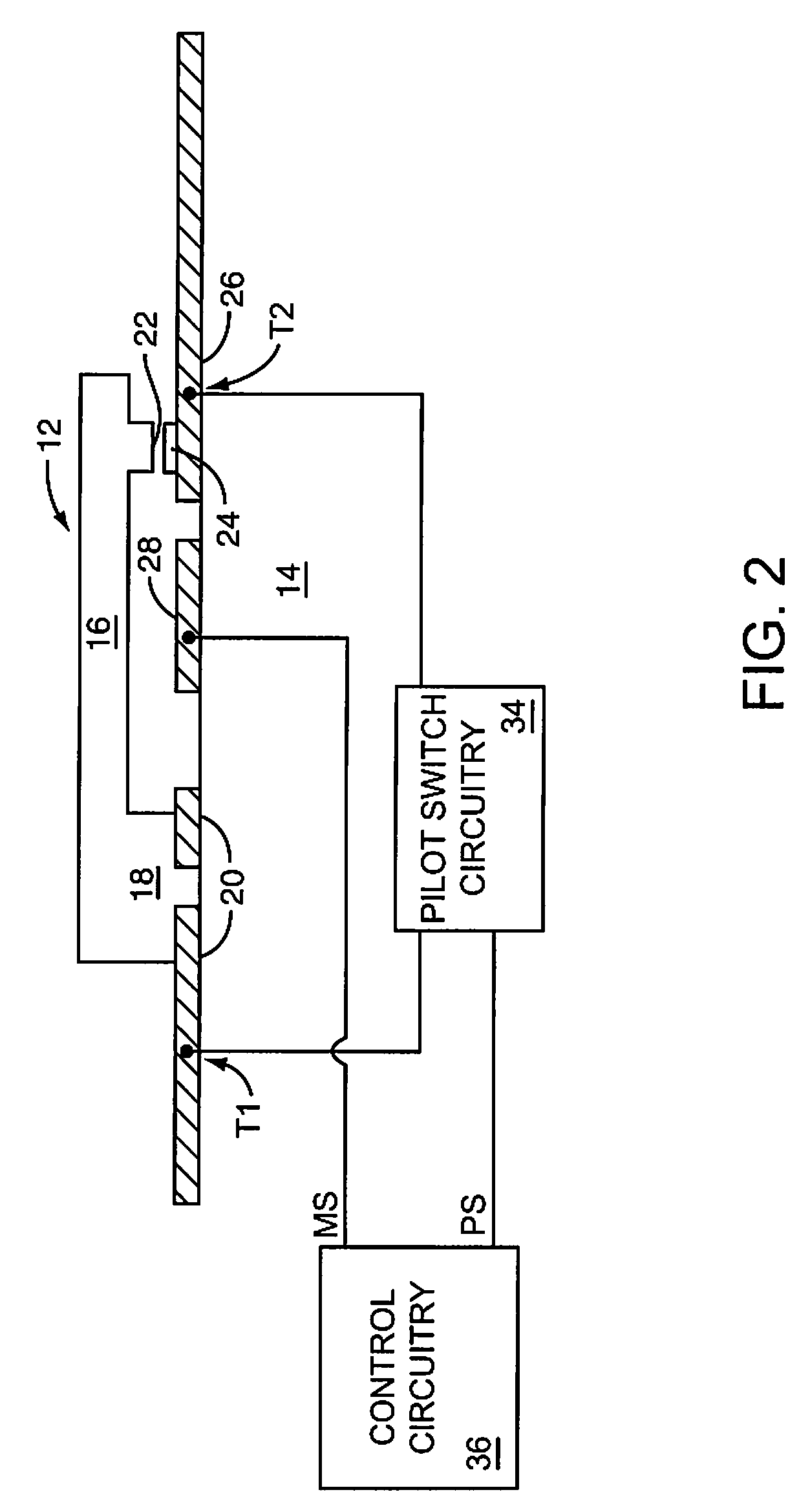
[0010]The present invention provides pilot switch circuitry that is coupled across first and second terminals of a microelectromechanical system (MEMS) switch to reduce or eliminate arcing between a cantilever contact and a terminal contact when the MEMS switch is opened or closed. The MEMS switch includes a cantilever that is connected to the first terminal at a first end and provides the cantilever contact at a second end. The cantilever moves the cantilever contact against the terminal contact when the MEMS switch is closed. The pilot switch circuitry establishes a common potential at the first and second terminals prior to, and preferably until, the cantilever contact and terminal contact come into contact with one another when the MEMS switch is closed. Providing a common potential at the first and second terminals provides a common potential at the cantilever contact and terminal contact as the MEMS switch is being closed, thereby reducing or eliminating arcing between the cantilever contact and the terminal contact. The pilot switch circuitry may also establish a common potential at the first and second terminals prior to, and preferably after, the cantilever contact and terminal contact separate from one another when the MEMS switch is opened.

Problems solved by technology

However, an FET switch may generate higher insertion loss than is generated by the main MEMS switch 12.
Moreover, at high power levels in an RF circuit (not shown), parasitic capacitance at the semiconductor junctions of the FET switch may alter RF signals.

Method used


Image

  • Pilot switch
  • Pilot switch
  • Pilot switch

Examples


first embodiment

[0041]FIG. 5A shows the circuit of FIG. 3C with the shunt switch circuitry 54 coupled in parallel between the first terminal T1 and ground. The shunt switch circuitry 54 comprises a termination resistance R1, a shunt FET 56, and a first shunt MEMS switch 58. The termination resistance R1 is shown coupled between the first terminal T1 and a drain of the shunt FET 56. In light of the inherent impedance of the shunt FET 56, the termination resistance R1 may optionally be omitted to provide an alternate short circuit to ground. A source of the shunt FET 56 is coupled to a fifth terminal T5, and a gate is coupled to the control circuitry 36. The gate is fed from a first shunt switch control signal SS1.

[0042]The first shunt MEMS switch 58 has a cantilever 60 coupled between a sixth terminal T6 and a cantilever contact 62. As shown in FIG. 5A, the sixth terminal T6 is coupled to ground. A terminal contact 64 is coupled to the fifth terminal T5. An actuator plate 66 is coupled to the contro...

second embodiment

[0046]FIG. 5B shows the circuit of FIG. 3C with shunt switch circuitry 54 coupled in parallel between the first terminal T1 and ground. The shunt switch circuitry 54 comprises the termination resistance R1, the shunt FET 56, and the first shunt MEMS switch 58, all described in FIG. 5A. Additionally, the shunt switch circuitry 54 further comprises a second shunt MEMS switch 68 having a cantilever 70 coupled between a seventh terminal T7 and a cantilever contact 72. As shown in FIG. 5B, the seventh terminal T7 is coupled to the sixth terminal T6, which is coupled to ground. A terminal contact 74 is coupled to an eighth terminal T8, which is also coupled to the drain of the shunt FET 56 and the termination resistance R1. An actuator plate 76 is coupled to the shunt switch circuitry 54 to be operable by a third shunt switch control signal SS3.

[0047]In operation, and similar to the description for FIG. 5A, the shunt switch circuitry 54 of FIG. 5B may be operated independently from the pi...


PUM


Abstract

Pilot switch circuitry coupled across first and second terminals of a microelectromechanical system (MEMS) switch is provided to reduce or eliminate arcing between a cantilever contact and a terminal contact when the MEMS switch is opened or closed. The pilot switch circuitry establishes a common potential at the first and second terminals prior to, and preferably until, the cantilever contact and terminal contact come into contact with one another when the MEMS switch is closed. The pilot switch circuitry may also establish a common potential at the first and second terminals prior to, and preferably after, the cantilever contact and terminal contact separate from one another when the MEMS switch is opened.

Description

FIELD OF THE INVENTION[0001]The present invention relates to microelectromechanical system (MEMS) switches, and in particular to pilot switch circuitry that reduces or eliminates arcing between MEMS switch contacts when the MEMS switch is opened or closed.BACKGROUND OF THE INVENTION[0002]As electronics evolve, there is an increased need for miniature switches that are provided on semiconductor substrates along with other semiconductor components to form various types of circuits. These miniature switches often act as relays, generally range in size from a micrometer to a millimeter, and are generally referred to as microelectromechanical system (MEMS) switches.[0003]In some applications, MEMS switches are configured as switches and replace field effect transistors (FETs). Such MEMS switches reduce insertion losses due to added resistance, and reduce parasitic capacitance and inductance inherent in providing FET switches in a signal path. MEMS switches are currently being deployed in...

Claims


Application Information

Patent Timeline
Patent Type & Authority Patents(United States)
IPC IPC(8): H01H9/30H01H73/18
CPCH01H9/30H01H9/542H01H59/0009
Inventor BAUDER, RUEDIGERCOONS, DAVID DURGINDENING, DAVID C.JORGENSON, JON D.
Owner QORVO US INC
Why Eureka
Try Eureka