
Dynamic logical data channel assignment using time-grouped allocations

a dynamic logical and time-grouped technology, applied in the field of data processing systems, can solve problems such as performance degradation, and achieve the effects of reducing false dependencies for unrelated data transfers, efficient allocation, and improving performan

Inactive Publication Date: 2011-01-04
INT BUSINESS MASCH CORP
View PDF7 Cites 5 Cited by
  • Summary
  • Abstract
  • Description
  • Claims
  • Application Information

AI Technical Summary

Benefits of technology

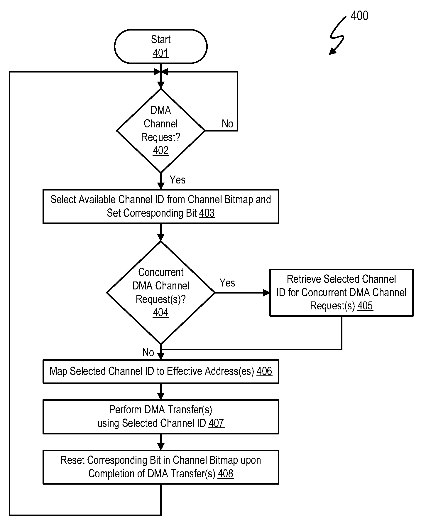
The patent describes a system and method for dynamically allocating logical channels for DMA transfers. This allows for efficient allocation of channels, deallocation, and reclamation under software control. By reusing channel IDs for allocations made within a certain period of time, false dependencies for unrelated data transfers are reduced and performance is improved. The system automatically assigns and records available channel IDs based on input values, and multiple DMA transfer requests can be efficiently allocated over a limited number of channel IDs. The method involves sequentially incrementing a DMA channel identifier counter over a plurality of time increments and allocating the current value of the counter in a first time increment for use in performing at least the first and second DMA transfer requests. The system also maps DMA transfer requests to the allocated DMA channel identifier to assist with waiting on the DMA transfer. The allocation of the DMA channel identifier is implemented by identifying an available DMA channel identifier in a channel bitmap and storing a predetermined value in the first bit position. The system allows for efficient allocation of channels, deallocation, and reclamation, reducing false dependencies and improving performance.

Problems solved by technology

This results in operations on unrelated data that can potentially map to the same logical channel, resulting in false dependencies, which may in turn result in performance degradation.

Method used


Image

  • Dynamic logical data channel assignment using time-grouped allocations
  • Dynamic logical data channel assignment using time-grouped allocations
  • Dynamic logical data channel assignment using time-grouped allocations

Examples


Embodiment Construction

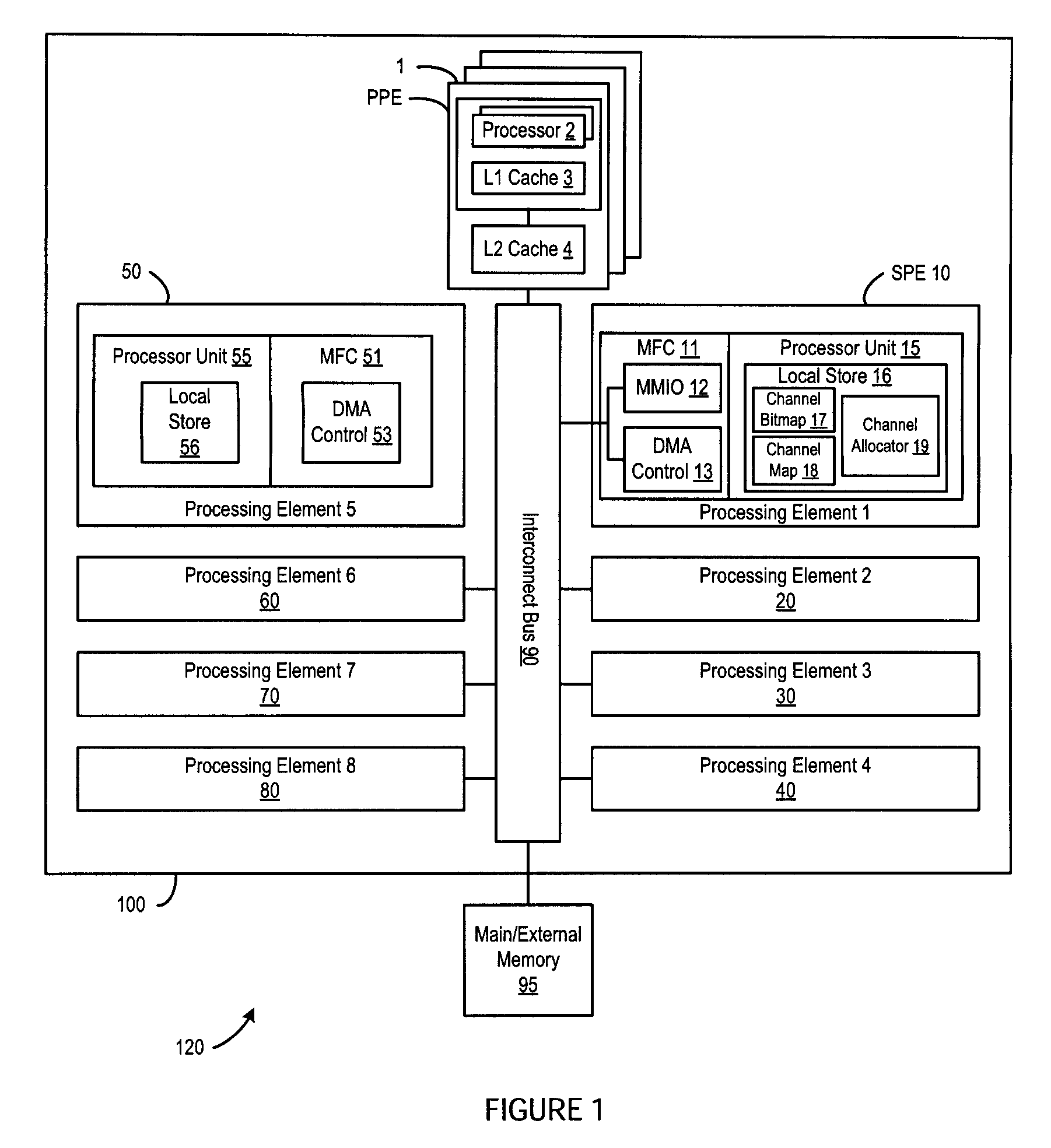
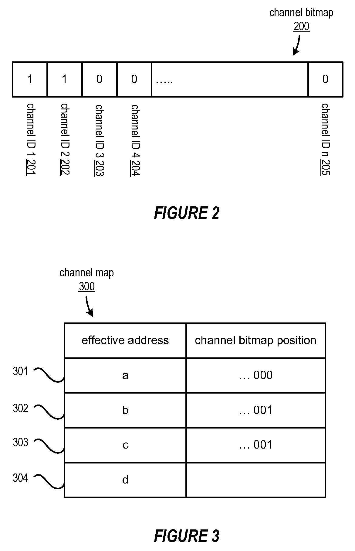
[0015]A method, system and program are disclosed for dynamically allocating logical channel identifiers to multiple DMA transfer requests that are grouped in time. In selected embodiments, the logical channel identifiers are allocated under software control using one or more multi-bit words as channel bitmaps, with each bit representing the availability of a DMA channel identifier, where the bit being set represents that the channel is in-use, and the bit being re-set represents that the channel is available for allocation. When a plurality of DMA transfers are initiated within a predetermined time increment, a first DMA channel identifier is selected and assigned to the first DMA transfer request, and any subsequent DMA transfer request(s) within the predetermined time increment are assigned the same channel identifier. In selected embodiments, an available DMA channel identifier is selected by finding a first bit position that is not set, and then setting it. The DMA channel ident...


PUM


Abstract

A method, system and program are provided for dynamically allocating DMA channel identifiers to multiple DMA transfer requests that are grouped in time by virtualizing DMA transfer requests into an available DMA channel identifier using a channel bitmap listing of available DMA channels to select and set an allocated DMA channel identifier. Once the input values associated with the DMA transfer requests are mapped to the selected DMA channel identifier, the DMA transfers are performed using the selected DMA channel identifier, which is then deallocated in the channel bitmap upon completion of the DMA transfers. When there is a request to wait for completion of the data transfers, the same input values are used with the mapping to wait on the appropriate logical channel. With this method, all available logical channels can be utilized with reduced instances of false-sharing.

Description

BACKGROUND OF THE INVENTION[0001]1. Field of the Invention[0002]The present invention is directed in general to the field of data processing systems. In one aspect, the present invention relates to direct memory access management within data processing systems.[0003]2. Description of the Related Art[0004]Data processing systems typically include one or more central processing units (CPU), one or more levels of caches, one or more external memory devices, and input / output (I / O) mechanisms, all interconnected via an interconnection of buses and bridges. In addition to these hardware components, data processing systems also include one or more software (or firmware) components, such as an Operating System (OS) and one or more programs which interact with the OS. To facilitate memory access operations, direct memory access (DMA) operations are used to provide data transfer operations (e.g., from external memory to a local cache memory) without requiring direct processor oversight and co...

Claims


Application Information

Patent Timeline
Patent Type & Authority Patents(United States)
IPC IPC(8): G06F13/28
CPCG06F13/28
Inventor MADRUGA, JOAQUINBURDICK, DEAN J.
Owner INT BUSINESS MASCH CORP
Learn More