Thin-section conveyor apparatus, thin-section scooping tool, and method for transporting thin sections

a conveyor and thin-section technology, applied in the directions of transportation and packaging, pile separation, instruments, etc., can solve the problems of thin-section thin-section adhesive loss, peeling off, color density detrimental to microscopic observations, etc., to reduce the possibility of entraining water and shorten the process time

Inactive Publication Date: 2011-01-11
SEIKO INSTR INC
View PDF22 Cites 13 Cited by
  • Summary
  • Abstract
  • Description
  • Claims
  • Application Information

AI Technical Summary

Benefits of technology

[0014]In accordance with the thin-section conveyor apparatus above, in the case the thin sections are transported to the liquid bath using the conveyor belt, the linear body extended along the direction of transportation of the conveyor belt gradually intrudes into the liquid from the front end. Accordingly, the linear body is fundamentally free of entraining air because it is sequentially soaked or get acquainted with water. In contrast to this, the linear body in the transverse direction, which is perpendicular to the transportation direction of the conveyor belt, is wholly immersed in the liquid of the liquid bath at the one time. Accordingly, the linear body in the transverse direction has very short time to get soaked or acquainted with the liquid, and these results in easy entrainment of air. In addition, the presence of a linear body in the transverse direction causes irregularities to generate in longitudinal linear body or transverse linear body itself at the part the transverse linear body crosses the perpendicular linear body; these irregularities easily entrain air.
[0043]Furthermore, because the thin sections once set afloat on the surface of the liquid plane can be scooped up and then floated again to the liquid surface after once releasing the bubbles that are entrained into the lower side of the thin sections, the bubbles that are present on the lower side can be effectively removed.

Problems solved by technology

Conventionally, the process step for taking out and sending the thus prepared thin sections to the next process has been carried out manually because the thin sections were extremely thin and were apt to suffer damages such as curls, wrinkles, breaks, and the like.
However, if bubbles should be entrained between the glass slide and the thin section, the adhesiveness of the thin sections to the glass slide decreases to cause the problem of peeling off in the subsequent dyeing step.
Otherwise, even if the thin section stay adhered without peeling off, the bubble-entrained part appears as a part differing in color density which is detrimental in microscopic observations.

Method used


Image

  • Thin-section conveyor apparatus, thin-section scooping tool, and method for transporting thin sections
  • Thin-section conveyor apparatus, thin-section scooping tool, and method for transporting thin sections
  • Thin-section conveyor apparatus, thin-section scooping tool, and method for transporting thin sections

Examples


example 1

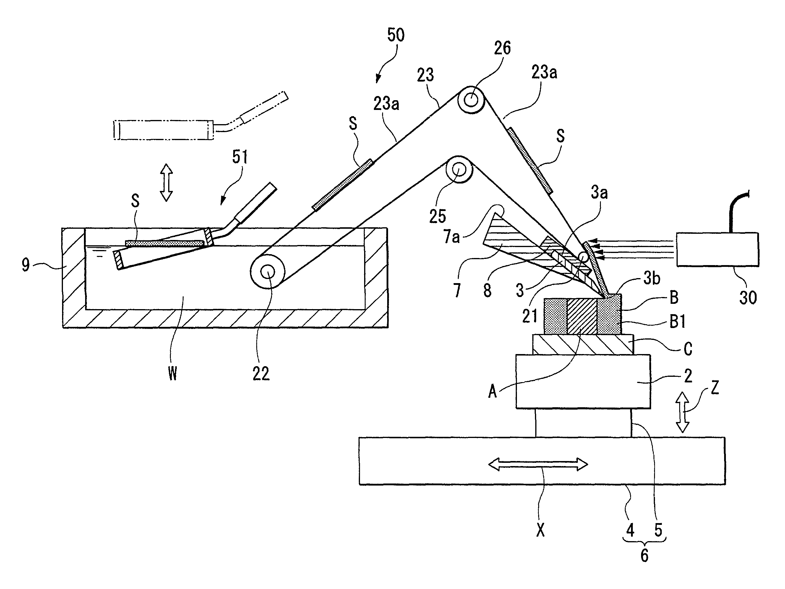
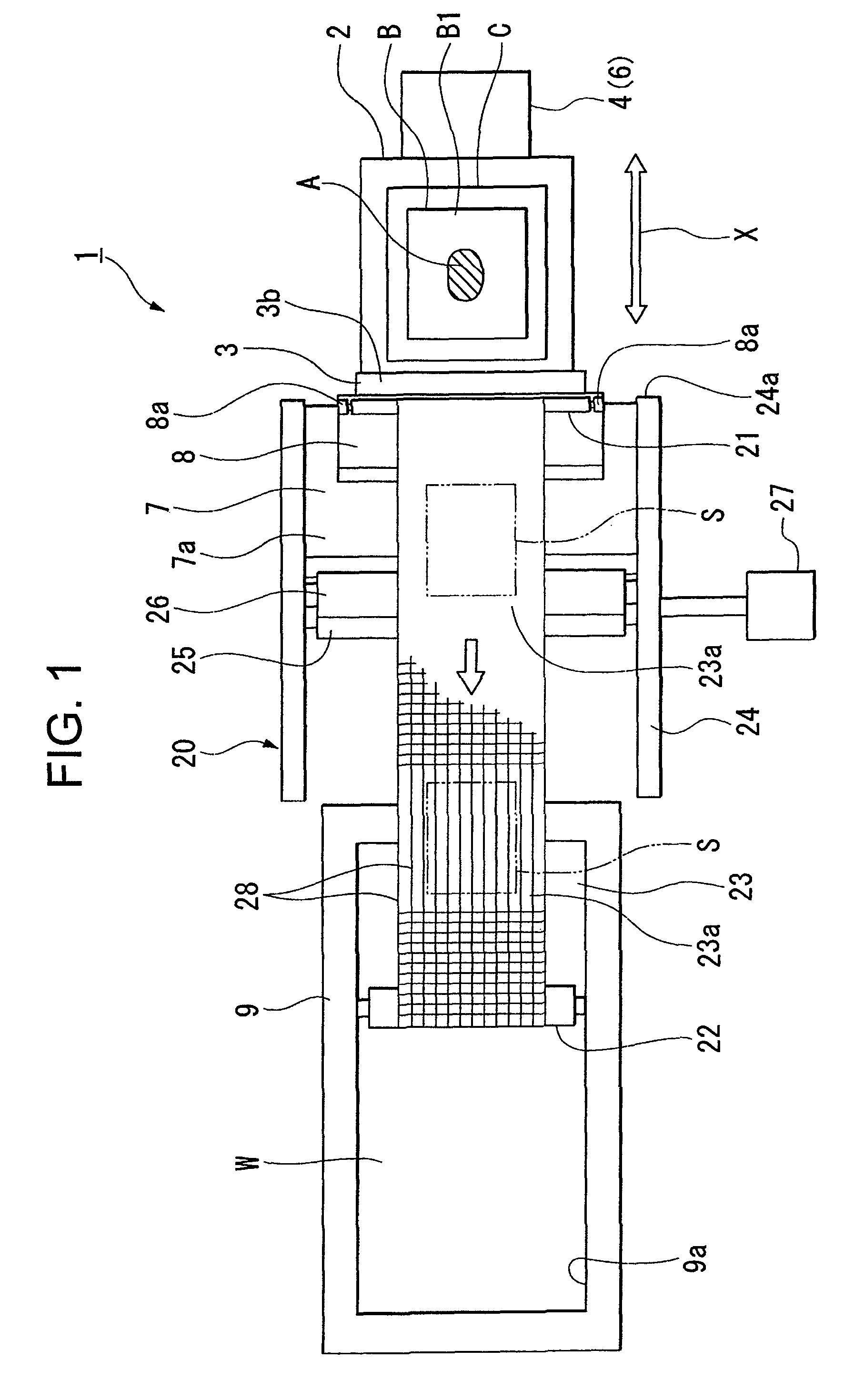
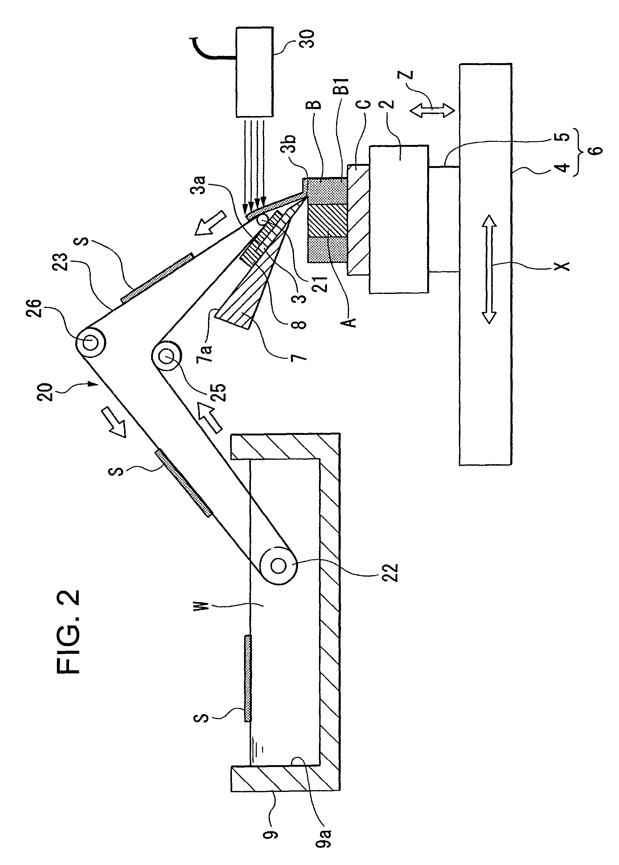
[0060]FIGS. 1 and 2 each show a thin-section manufacturing system equipped with a thin-section conveyor apparatus according to the invention, wherein FIG. 1 is a plan view of the thin-section manufacturing system and FIG. 2 is the side view of the thin-section manufacturing system. The thin-section manufacturing system 1 shown in these figures prepares ultra-thin thin sections about 3 to 5 μm in thickness from an embedded block B containing embedded therein a biological sample A, and, in the inspection and observation step for the biological sample A, it automatically cuts out thin sections from the embedded block B and transfers them to the next process step. The biological sample A may be a tissue of an organ and the like that has been taken from human bodies, laboratory animals, and the like, which are properly selected in accordance with the fields of interest, such as medical field, pharmaceutical field, food field, and biological field. The embedded block B is such produced by...

modified example

[0080]In the first embodiment, the conveyor belt 23 comprises a part 23a for mounting thin sections on the conveyor belt 23, which is made of warps 28 alone; however, the invention is not only limited thereto, and the part 23a for mounting the thin sections on the conveyor belt 23 may be such having wefts 29 at a density lower than in the other parts.

[0081]Furthermore, in the first embodiment above, the part 23a for mounting thin sections S was made solely of the warps 28 which constitute the conveyor belt 23; however, the invention is not only limited thereto, and the part 23a for mounting thin sections S thereon may be constituted, as shown in FIG. 5, by perforating a hole 31 in a part of the conveyor belt 23, and attaching warps (linear body) 32 extended along the direction of transportation of the conveyor belt 23, in such a manner that they may be disposed in parallel and with predetermined intervals taken among them. In this case, the conveyor belt 23 need not be a cloth, but ...

example 2

[0083]FIGS. 6 and 7 show a thin-section manufacturing system equipped with a thin-section conveyor apparatus according to the invention. FIG. 6 is a plan view, and FIG. 7 is a side view partially cross sectioned. In the present embodiment, the same members as those used in the aforementioned examples are indicated with the same symbols to omit their explanations.

[0084]Referring to FIG. 6, the thin-section manufacturing system 40 described in the present embodiment comprises a cutter 3 provided at a draw angle θ with respect to the axial line L perpendicular to the direction of transportation X. The conveyor unit (thin-section conveyor apparatus) 41 is equipped with a direction switching roller (starting point roller) 21 and a rear roller (ending point roller) 42, and a conveyor belt 43 wound around the rollers 21 and 42. Furthermore, the rear roller 42 is axially fixed in a rotatable manner to a frame not shown, and supports conveyor belt 43 so that the belt may be run in the direct...


PUM

PropertyMeasurementUnit
thicknessaaaaaaaaaa
angleaaaaaaaaaa
angleaaaaaaaaaa

Abstract

A thin-section conveyor apparatus for transporting thin sections that have been prepared by thinly cutting an embedded block, which transports the thin sections to a liquid bath by mounting them on the upper plane of a conveyor belt having a longitudinal linear body extended along the direction of transportation and a transverse linear body disposed perpendicular to the longitudinal linear body, provided that the density of the transverse linear body for the part on which the thin sections are to be mounted is lower than that of the transverse linear body of the other places. It provides thin sections almost free of entraining bubbles. A thin-section scooping tool and a method for transporting thin sections are also proposed.

Description

[0001]This application claims priority under 35 U.S.C. §119 to Japanese Patent Application Nos. JP2006-206427 filed Jul. 28, 2006, and JP2007-127858 filed May 14, 2007, the entire content of which is hereby incorporated by reference.BACKGROUND OF THE INVENTION[0002]1. Field of the Invention[0003]The present invention relates to a thin-section conveyor apparatus for transporting thin sections obtained by thinly cutting embedded blocks having embedded therein the biological samples taken out from human bodies, laboratory animals, and the like, as well as to a thin-section scooping tool for scooping thin sections that are floating on the liquid surface in a bath, and to a method for transporting thin sections utilizing the thin-section conveyor apparatus.[0004]2. Description of the Related Arts[0005]As a method for testing and observing biological samples taken from human bodies or laboratory animals and the like, conventionally known is a method which comprises preparing an embedded b...

Claims


Application Information

Patent Timeline
Patent Type & Authority Patents(United States)
IPC IPC(8): B65G15/30G01N1/06G01N35/04
CPCG01N1/06G01N1/312G01N1/4077G01N35/00009G01N35/04
Inventor MIYATANI, TATSUYAFUJIMOTO, KOJIITO, TETSUMASA
Owner SEIKO INSTR INC
Why Eureka
Try Eureka