Traction band

a technology of traction bands and lugs, which is applied in the direction of driving belts, belts/chains/gearrings, mechanical equipment, etc., can solve the problems of difficulty in achieving the durability of existing tracked vehicles, generally inability to efficiently operate pneumatic tires on such soft surfaces, and generally not having a very good durability on hard surfaces. , to achieve the effect of reducing rolling resistance and thereby fuel consumption, substantial continuity and structural integrity of traction lugs, and reducing energy

Active Publication Date: 2011-01-11
SOUCY INT
View PDF16 Cites 23 Cited by
  • Summary
  • Abstract
  • Description
  • Claims
  • Application Information

AI Technical Summary

Benefits of technology

[0015]The skilled addressee will readily understand that the alignment of the thinner bending regions with the regions which are devoid of drive lugs (and guide lugs) on the inner surface reduces the energy required to bend or flex the traction band around the various wheels of the track system. Consequently, the traction band of the present invention reduces rolling resistance and thereby fuel consumption.
[0016]In addition, the thinner bending regions, as opposed to the prior art complete partition of the traction lugs, maintain substantial continuity and structural integrity of the tractions lugs, thereby preserving the particular advantages of the traction lugs (e.g. soil and debris evacuation, traction, etc.).

Problems solved by technology

Pneumatic tires are generally incapable of efficient operation on such soft surfaces as they tend to burrow into the surface rather than riding across the surface.
Still, difficulties are encountered with existing tracked vehicles.
Tread patterns adapted to be used on soft surfaces have also been developed, but they generally do not have a very good durability on hard surfaces.
However, due to the configuration of the chevrons, conventional chevron tread patterns typically suffer from requiring more energy to bend the track thereby increasing rolling resistance and ultimately, fuel consumption.
However, these cuts significantly reduce the structural integrity of the traction lugs and thus of the track and ultimately produce only limited results.

Method used


Image

  • Traction band
  • Traction band
  • Traction band

Examples


Embodiment Construction

[0025]A novel traction band will be described hereinafter. Although the invention is described in terms of specific illustrative embodiments, it is to be understood that the embodiments described herein are by way of example only and that the scope of the invention is not intended to be limited thereby.

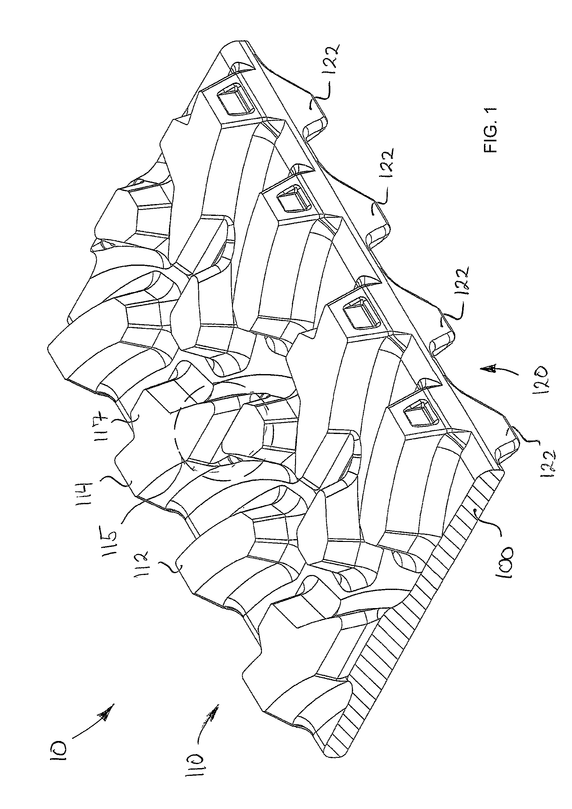
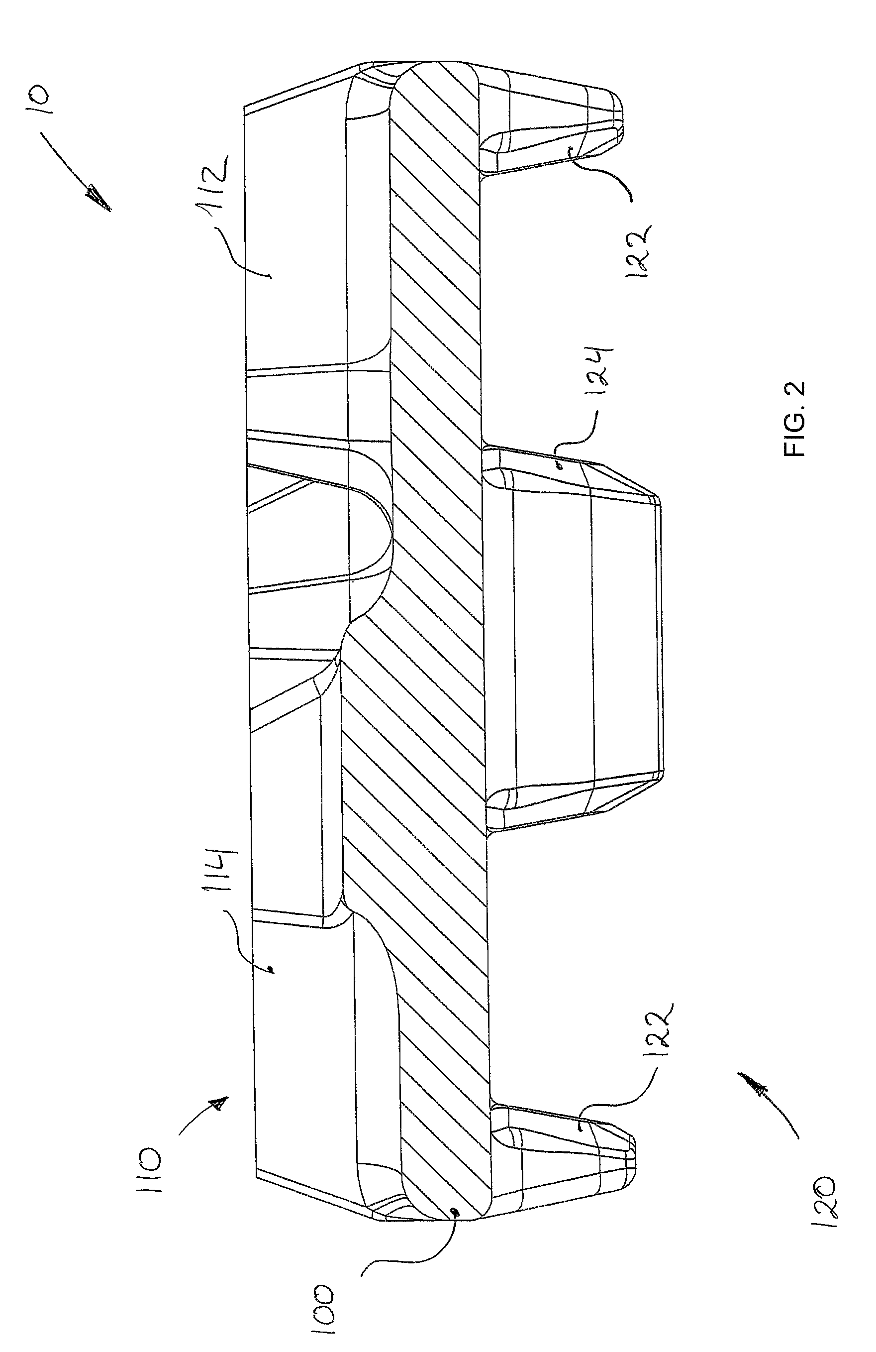
[0026]Referring first to FIGS. 1 and 2, an exemplary traction band 10 incorporating the principles of the invention is illustrated. The traction band 10 is generally adapted to be used with a track system such as the track system 200 shown in FIG. 6. Track systems such as track system 200 are generally known in the art and need not be further described.

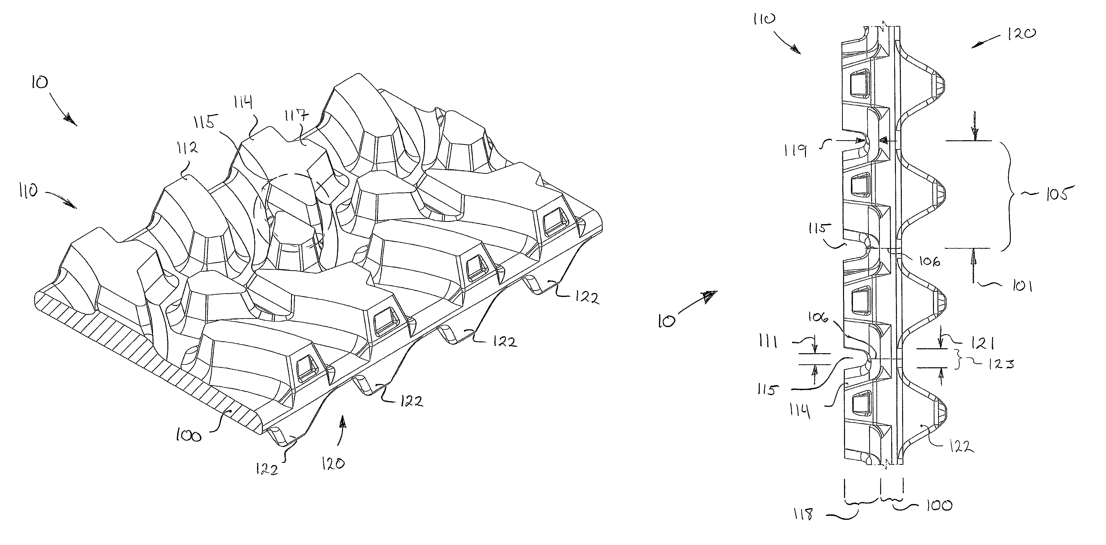
[0027]The traction band 10 typically comprises a main band body 100 divided into a plurality of band sections 105 (FIGS. 3-5) attached together, usually unitarily, along laterally extending pitch lines 106. The band body 100, preferably made from reinforced elastomeric material, has an external or outer ground-engaging surface 110 and a...


PUM


Abstract

A traction band substantially made from elastomeric material is disclosed. The traction band comprises a main band body divided into a plurality of sections connected together along laterally extending pitch lines. The band body has an interior wheel-engaging surface, adapted to cooperate with the various wheels of a track system, and an exterior ground-engaging surface adapted to engage the ground. The wheel-engaging surface comprises one or more rows of longitudinally spaced-apart drive lugs and / or guide lugs typically disposed on each of the band sections. The ground-engaging surface comprises traction lugs extending longitudinally across more than one band section, these traction lugs comprising laterally extending bending regions where the traction lugs are thinner. These bending regions are substantially aligned with regions on the interior surface which are devoid of drive lugs and guide lugs.

Description

CROSS-REFERENCE TO RELATED APPLICATIONS[0001]There are no cross-related applications.FIELD OF THE INVENTION[0002]The present invention generally relates to traction bands and endless tracks for use on tracked vehicles. More particularly, but not exclusively, the present invention relates to traction bands and endless tracks for use on agricultural, construction and forestry vehicles and other similar tracked vehicles.BACKGROUND OF THE INVENTION[0003]Numerous types of vehicles are frequently used on terrain on which it is difficult for pneumatic tires to operate. Both military vehicles, such as tanks and armored personal vehicles, and civilian vehicles, such as tractors and recreational vehicles, are operated on terrains, such as sand surfaces, which are very soft. Pneumatic tires are generally incapable of efficient operation on such soft surfaces as they tend to burrow into the surface rather than riding across the surface.[0004]Tracked vehicles have been developed for use on terra...

Claims


Application Information

Patent Timeline
Patent Type & Authority Patents(United States)
IPC IPC(8): B60B15/00
CPCB62D55/0842B62D55/24B62D55/244
Inventor LEMAIRE, MARC-ANDREFAUCHER, CLAUDEST-PIERRE, YVES
Owner SOUCY INT
Why Eureka
Try Eureka