Laser illuminated backlight for flat panel displays

a technology of backlight and flat panel display, which is applied in the direction of planar/plate-like light guides, lighting and heating apparatus, instruments, etc., can solve the problems of further loss of efficiency, reduced image resolution, and unacceptable image artifacts, and achieve the effect of reducing speckles

Active Publication Date: 2011-01-11
DOLBY LAB LICENSING CORP +1
View PDF20 Cites 79 Cited by
  • Summary
  • Abstract
  • Description
  • Claims
  • Application Information

AI Technical Summary

Problems solved by technology

Unfortunately, narrow band light incident on random rough surfaces also introduces an unacceptable image artifact known as “speckle”.
The visual effects of speckle detract from the aesthetic quality of an image and also result in a reduction of image resolution.
A variety of “de-speckling” techniques can be used to reduce this artifact to “acceptable levels”, but only at the expense of a further loss in efficiency, which negatively impacts cost, reliability, package size, and power consumption.
Known speckle reduction techniques tend to disturb the spatial or temporal coherence of laser beams through optical path randomization and / or spectral broadening.
However, most of these solutions are expensive and technically complex, relying, for example, on mode-locking techniques to produce very short pulses in the order of 1 ps to increase the optical bandwidth.

Method used


Image

  • Laser illuminated backlight for flat panel displays
  • Laser illuminated backlight for flat panel displays
  • Laser illuminated backlight for flat panel displays

Examples


Embodiment Construction

[0028]To provide an overall understanding of the invention, certain illustrative embodiments will now be described, including a bandwidth-enhanced laser light source for flat-panel displays, such as liquid crystal displays (LCDs). However, it will be understood by one of ordinary skill in the art that the apparatus described herein may be adapted and modified as is appropriate for the application being addressed and that the systems and methods described herein may be employed in other suitable applications, and that such other additions and modifications will not depart from the scope hereof.

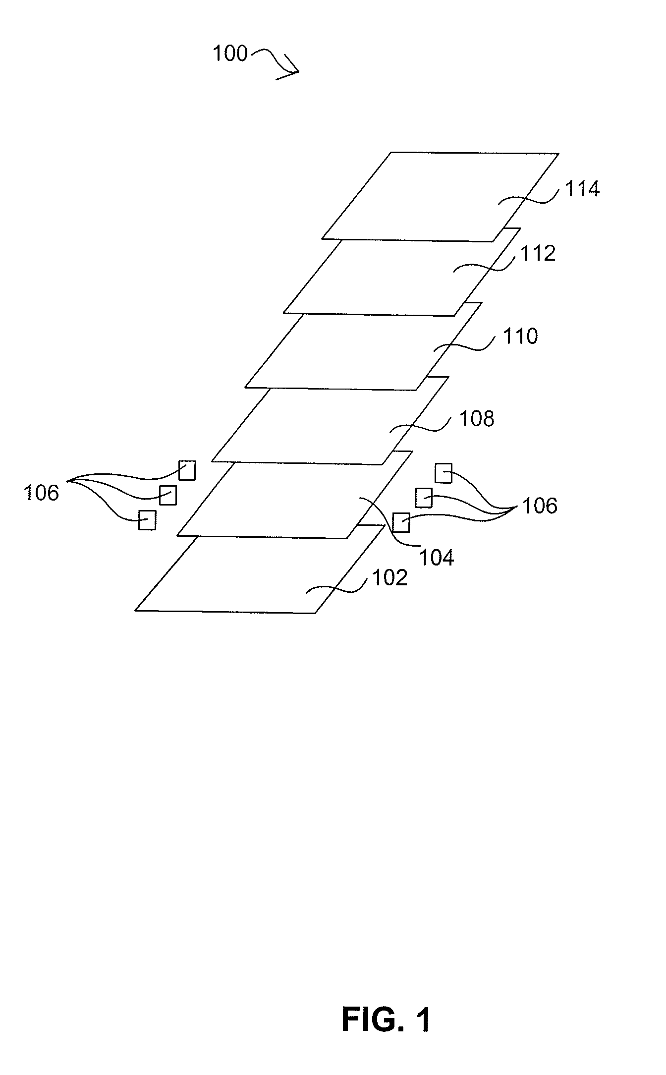
[0029]FIG. 1 shows schematically the layers of a liquid crystal display (LCD) screen 100, according to an illustrative embodiment of the invention. At the back is a reflector 102 for directing light toward the front of the display. Light from the reflector passes through a light guide 104, usually made of molded transparent or white plastic. In one implementation, the light guide 104 has a plur...


PUM


Abstract

Laser lit flat panel displays are disclosed including edge-lit and direct lit backlights. In certain embodiments, laser assemblies are selected to obtain bandwidth distributions to reduce speckle.

Description

CROSS REFERENCE TO RELATED APPLICATIONS[0001]This application claims the benefit of U.S. Provisional Application Ser. No. 61 / 000,475, filed Oct. 26, 2007, the entire contents of which are incorporated herein by reference.BACKGROUND OF THE INVENTION[0002]Red, green, and blue (RGB) lasers offer demonstrable benefits over fluorescent lamps and light emitting diodes for high-performance imaging applications. Greater color saturation, contrast, sharpness, and color-gamut are among the most compelling attributes distinguishing laser displays from conventional imaging systems.[0003]To compare laser illumination technology with conventional technologies, it is instructive to examine two fundamental parameters which relate to their ultimate practicality. The first parameter can be defined as optical efficiency—in this case, the lumens of output per watt of input to the light source. The second is cost compatibility, that is, the extent to which the technology in question yields a cost effect...

Claims


Application Information

Patent Timeline
Patent Type & Authority Patents(United States)
IPC IPC(8): F21V7/04
CPCG02B27/48G02B6/0078G02B6/0068G02B6/003
Inventor KARAKAWA, MASAYUKI
Owner DOLBY LAB LICENSING CORP
Why Eureka
Try Eureka