
System and method comprising same for measurement and/or analysis of particles in gas stream

a gas stream and system technology, applied in the field of system and method for sampling a gas feed stream, can solve the problems of low yield in the device manufacturing process, reliability problems, and non-uniform particulate distribution

Inactive Publication Date: 2011-01-11
VERSUM MATERIALS US LLC
View PDF112 Cites 13 Cited by
  • Summary
  • Abstract
  • Description
  • Claims
  • Application Information

AI Technical Summary

Problems solved by technology

For example, particulate contamination in fabricating materials causes low yield in the device fabrication process, and reliability problems in finished semiconductor devices.
Such effects produce non-uniform particulate distributions, including stratification, in the supply vessel.
In addition to the above issues, if the gas feed stream comprises a reactive gas such as, for example, silane, the reactive gas may combine with atmospheric contaminants to form suspended solid material (particles).
These solid reaction products can produce a significant inaccuracy in any measurement of the suspended particle content.
However, due to the pressure limitations of available instrumentation, it may not be practical to measure the particle content at the full pressure of the storage vessel.
These particles cannot be easily vaporized through heating.
Further, in certain instances, the process of pressure reduction frequently produces sub-critical conditions in the gas.
The pressure reduction process therefore substantially degrades the accuracy of particle measurement.
These instruments, however, cannot provide information on composition and morphology of the measured particles.
However, this is an expensive and difficult modification to the instrument design and therefore suffers from practical problems.
However, this test method cannot discriminate between particles originating in the gas supply source and those spurious particles formed in the sampling system.
Therefore, the actual particle content in the pressurized vessel cannot be accurately determined downstream of a bed-type purifier.
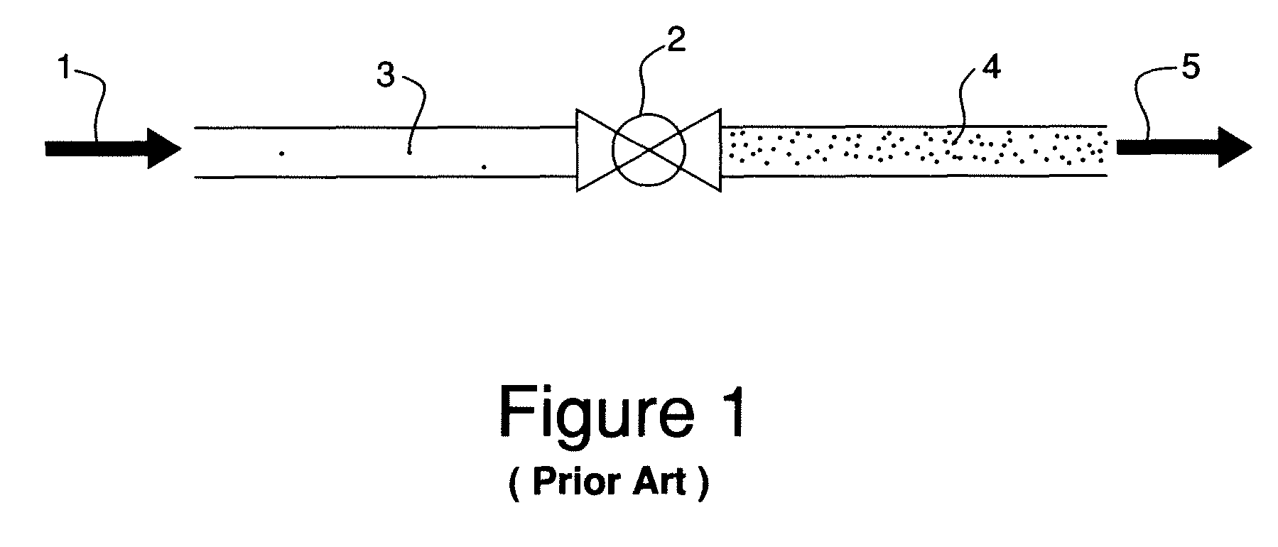
This method is usually not effective in preventing the formation of nucleated particles in the expanded gas stream.

Method used


Image

  • System and method comprising same for measurement and/or analysis of particles in gas stream
  • System and method comprising same for measurement and/or analysis of particles in gas stream
  • System and method comprising same for measurement and/or analysis of particles in gas stream

Examples


example 1

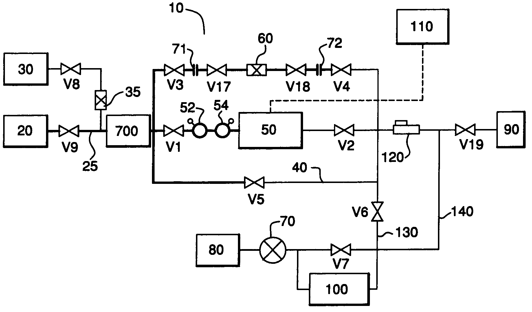
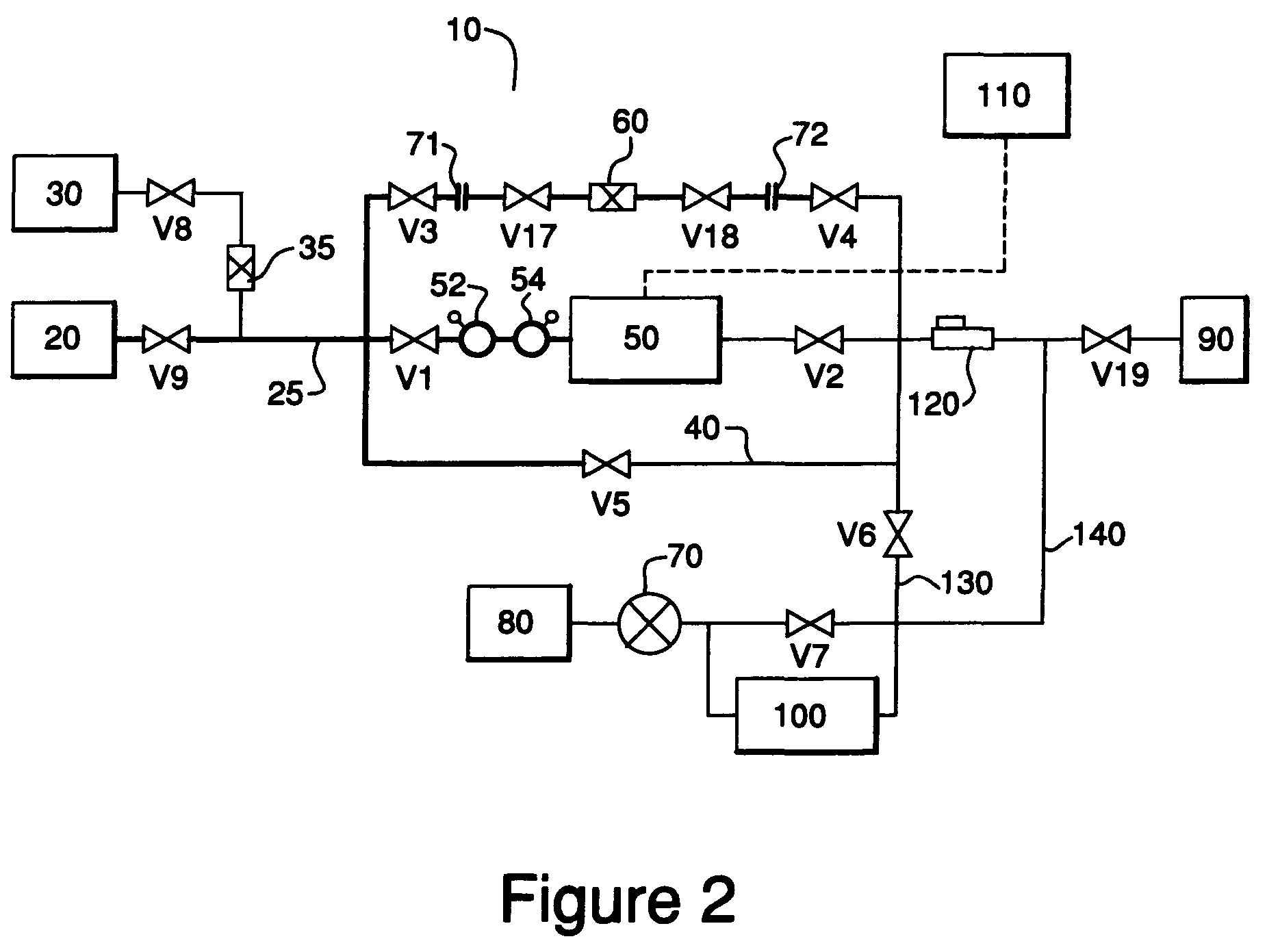
[0066]A particle counting system of the type shown in FIGS. 2 and 3 was connected to various compressed gas cylinders. A pressure and corrosion resistant particle counter [Particle Measuring Systems (PMS), Inc. model Cylinder Gas System (CGS) M100] was used in the system. Therefore, no reduction in sample pressure was required upstream of the instrument. This instrument measures particles as small as 0.16 micrometer in size suspended in gas sample streams. Sample gas was withdrawn from each cylinder at a flow rate of 19 actual cm3 / min. and passed through the instrument. No particle capture filter was used in these tests. No filtration of the sample gas was made upstream of the instrument. Heat tracing of the sample lines, typically to 50° C., was used to minimize droplet formation in condensable gases, and to maintain a low moisture content in the sample line tubing. Sample gas pressure reduction, flow control, abatement and venting were provided downstream of the instrument. The sa...

example 2

[0069]A particle counting system of the type described in this patent application was connected to a compressed SiH4 (silane) gas cylinder. No filtration of the sample gas was made upstream of the instrument or particle capture filter. Heat tracing of the sample lines, typically to 50° C., was used to maintain a low moisture content in the sample line tubing. Sample gas flow control and abatement were provided downstream of the particle counter and particle capture filter. The sampling system was pressure cycled and heated to remove atmospheric contaminants prior to sampling.

[0070]A pressure resistant particle counter [Particle Measuring Systems (PMS), Inc. model Cylinder Gas System (CGS) M100, Particle Measuring Systems, Inc., Boulder, Colo.] was used in the system. Therefore, no reduction in sample pressure was required upstream of the instrument. This instrument measures particles as small as 0.16 micrometer in size suspended in gas sample streams. Sample gas was withdrawn from t...


PUM

PropertyMeasurementUnit
critical pointsaaaaaaaaaa
sizeaaaaaaaaaa
sizeaaaaaaaaaa

Abstract

A system and method for measuring and analyzing particles within a gas feed stream. In one aspect, the system includes a particle counter and a particle capture filter that are arranged in parallel. In another aspect, the system includes a purifying device to remove trace molecular impurities from a gas feed stream to reduce the presence of impurities.

Description

CROSS-REFERENCE TO RELATED APPLICATIONS[0001]This application claims the benefit of priority under 35 U.S.C. §119(e) to earlier filed U.S. patent application Ser. No. 60 / 649,490 filed on Feb. 3, 2005, and to earlier filed U.S. patent application Ser. No. 60 / 723,619 filed on Oct. 4, 2005, the disclosures of which are incorporated herein by reference.BACKGROUND OF THE INVENTION[0002]The present invention relates to a system and method for sampling a gas feed stream to determine the presence and characteristics of particulate contaminants in the gas stream. In particular, the present invention relates to a system comprising a particle counter and a particle capture filter, wherein the particle capture filter is advantageously arranged in parallel with the particle counter.[0003]Many users of specialty gases, such as semiconductor device manufacturers, require low suspended particle content in the gases. For example, particulate contamination in fabricating materials causes low yield in...

Claims


Application Information

Patent Timeline
Patent Type & Authority Patents(United States)
IPC IPC(8): G01N1/22
CPCG01N1/2205G01N15/00G01N1/34G01N15/0205Y10T436/25375Y10T436/25875Y10T436/25125Y10T436/255Y10T436/25G01N15/0606
Inventor MCDERMOTT, WAYNE THOMASOCKOVIC, RICHARD CARLROTH, DEAN VAN-JOHN
Owner VERSUM MATERIALS US LLC
Learn More