Packet transmission method and packet transmission device

a packet transmission and packet technology, applied in the field of packet transmission methods and packet transmission devices, can solve problems such as failure detection, and achieve the effects of high reliability of packet networks, high reliability of networks, and high reliability of networks

Active Publication Date: 2011-01-11
NIPPON TELEGRAPH & TELEPHONE CORP
View PDF21 Cites 53 Cited by
  • Summary
  • Abstract
  • Description
  • Claims
  • Application Information

AI Technical Summary

Benefits of technology

[0105]According to the present invention, in a packet network that could not be recovered uninterruptedly in an event of a failure in the past, copies of a packet is generated and the copies are transferred over different route respectively, and, in the receiving side, one of the two copies is transferred to realize uninterruptible switching function so that a highly reliable packet network can be provided. In addition, by using the independent route for each send / receive, a highly reliable packet network similar to point-point can be provided for communications among a plurality of sites.
[0106]In addition, according to the present invention, since a packet that requires high reliability and a packet that does not require it can be identified by referring to information in a packet header, the present invention can be used to networks of users having various requirements for reliability.
[0107]In addition, when the sameness of packets is determined in the receiving side, by using a value obtained by applying a predetermined function to a packet, high reliability of the network can be realized without inserting an excessive field to a packet.
[0108]In addition, in the receiving side, by performing transfer of a packet after waiting for arrival of the same packets from equal to or more than two routes, in a case when a packet is sent from one source to a plurality of destinations, skip of sequence due to arrival delay can be prevented even when the sequence identifier becomes discontinuous.
[0109]In addition, by providing a route identifier corresponding to a user priority, priority control can be performed in the relay network.

Problems solved by technology

The primary switch sends “Hello packet” over the ring, and a failure is detected if the packet does not return to the secondary switch within a predetermined time.
Further, as an uninterruptible technology for ATM cells in an ATM line, there is a method for writing a cell number on the ATM cell, copying the cell into equal to or more than two, sending each cell to different lines, and in the receiving side, selecting one of the same information cells sent from equal to or more than two lines to transfer the cell downstream (refer to patent document 1, for example).

Method used


Image

  • Packet transmission method and packet transmission device
  • Packet transmission method and packet transmission device
  • Packet transmission method and packet transmission device

Examples


second embodiment

[0235]In this embodiment, an apparatus configuration shown in FIG. 8 or FIG. 13 in the first embodiment is used. However, although a FIFO or a circulating FIFO is used for the memory A 122A and the memory B 122B in the first embodiment, a circulating hash is used in this embodiment.

[0236]FIG. 14 is a figure for explaining a case when using the circulating hash as the memory in the second embodiment of the present invention.

[0237]In the circulating hash, a given memory region is divided into n (an integer), and 1˜n are provided as addresses. As to a packet sent from the wide area network, the counter value is referred to, and the packet is stored in a memory region whose address is a remainder of the counter value when divided by n. For storing the packet, as long as the packet includes the data (payload) region in the L2 header, the route identifier region, the counter region, and the data (payload) region, the whole parts of the packet may be stored or some parts of them may be sel...

third embodiment

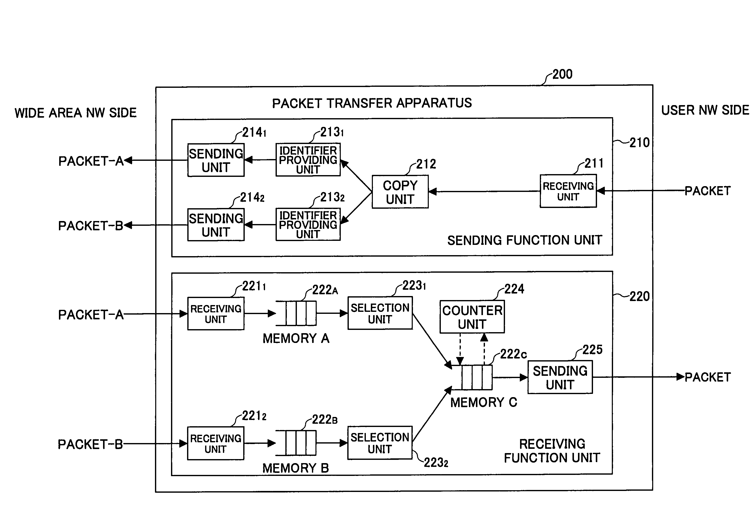
[0247]FIG. 16 is a figure showing a configuration of a packet transfer apparatus in the third embodiment of the present invention.

[0248]The packet transfer apparatus 200 shown in the figure includes a sending function unit 210 and a receiving function unit 220.

[0249]The sending function unit 210 includes a receiving unit 211, a copy unit 212, encoding units 2131 and 2132, and sending units 2141 and 2142. The configuration is the same as one of the first embodiment shown in FIG. 8.

[0250]The receiving function unit 220 includes receiving units 2211 and 2212, a memory A 222A, a memory B 222B, selection units 2231 and 2232, a counter unit 224, and a sending unit 225. The receiving function unit 220 receives packets by the receiving units 2211 and 2212, and writes each packet into the memory A 222A or the memory B 222B. Each of the memory A 222A and the memory B 222B is used as FIFO.

[0251]The selection units 2231 and 2232 read data from the memory A 222A and the memory B 222B, and transf...

fourth embodiment

[0270]Next, a redundancy configuration in the fourth embodiment is described. In fourth-tenth embodiments, a case in which the packet transfer apparatus is applied on the Ethernet is described as an example. By the way, although the configuration of the sending side apparatus and the receiving side apparatus in the following description may be any one of the before-mentioned first-third embodiments, it is not necessary to identify the send / receive pair in this embodiment.

[0271]FIG. 20(A) shows a configuration for realizing redundancy for all Ethernet packets. The copy unit in the sending side apparatus generates two copies of a send packet. Then, the identifier providing unit newly provides a VLAN tag (“VLAN-A” in the figure) and a sequence number for identifying the same sending sequence to each copy, and the two copies are sent to different networks respectively from the sending units. The selection units in the receiving side apparatus select one that arrives first in the packets...


PUM


Abstract

A packet transfer method in a network apparatus that transfers packets is disclosed. In the packet transfer method, a sending side apparatus generates two copies of a send packet, provides a sequence number identifying the same sending sequence to each of the copied packets, provides an identifier corresponding to a send / receive pair to each of the copied packets to send the packets, and a receiving side apparatus receives each of the packets with two receiving units; recognizes the identifiers each corresponding to a send / receive pair; identifies packets having the same information and the sequence based on the sequence number when the identifiers are the same; selects one of the packets of the same sequence so as to send the packet downstream, and discards another packet, wherein, when only one of the packets of the same sequence arrives, the arriving packet is sent downstream.

Description

TECHNICAL FIELD[0001]The present invention relates to a packet transfer method and a packet transfer apparatus. More particularly, the present invention relates to a packet transfer method and a packet transfer apparatus for realizing failure recovery without packet loss in a network adopting an Ethernet transfer scheme, a MPLS transfer scheme, GRE encapsulating, IPinIP encapsulating, GFP encapsulating, an encapsulation transfer scheme for variable length packet such as layer 2 frame encapsulating, and the like.BACKGROUND ART[0002]As conventional failure detection / switching technologies in packet communications, there are STP (Spanning Tree Protocol) in the Ethernet, derivatives of it (refer to non-patent documents 1-3, for example), and EAPS (Ethernet Automatic Protection Switching). In the EAPS, there is a technology for performing switching at high speed in a ring topology for a MAN service.[0003]In this technology, master switches are selected in the ring so that one of the mast...

Claims


Application Information

Patent Timeline
Patent Type & Authority Patents(United States)
IPC IPC(8): H04L12/28H04L45/28
CPCH04L1/08H04L45/24H04L45/00H04L12/4645H04L1/18
Inventor SHAKE, IPPEIFUKUTOKU, MITSUNORIIMAJYUKU, WATARUSHIMANO, KATSUHIRO
Owner NIPPON TELEGRAPH & TELEPHONE CORP
Why Eureka
Try Eureka