Optical access network apparatus and data signal sending method therefor

a technology of optical access network and data signal, which is applied in the field of optical access network apparatus and its data signal sending method, can solve the problems of increasing the cost of facility investment, affecting the transmission characteristics and data transmission speed, and no system has been proposed for protecting a portion of the pon interface board. , to achieve the effect of improving convenience or ease of facility maintenance management, reducing the number of devices, and flexible setting

Active Publication Date: 2007-03-22
NEC CORP
View PDF4 Cites 15 Cited by
  • Summary
  • Abstract
  • Description
  • Claims
  • Application Information

AI Technical Summary

Benefits of technology

[0026] According to the present invention, the data signal of the subscriber terminal is received via the PON interface, and the path management table is referred to, whereby when this data signal is transmitted to the network, it is possible to select a way of transmitting the data signal, i.e. concentrate or non-concentrate. That is, the path can be flexibly ...

Problems solved by technology

However, as the xDSL technology involves the packet communication using the telephone cable, it has a problem that the transmission characteristics and the data transmission speed are affected by the length of the telephone cable, the characteristics of the telephone cable, and the peripheral environmental conditions of wiring path of the telephone cable from a telephone switching office to the subscriber's premises.
However, no system has been proposed yet for protecting a portion relating to the PON interface boards and the SNI ports at the time of fault.
A first problem is that the cost of facility investment is increased when redundant configuration facilities are provided for the network element of network side in the conventional optical acces...

Method used


Image

  • Optical access network apparatus and data signal sending method therefor
  • Optical access network apparatus and data signal sending method therefor
  • Optical access network apparatus and data signal sending method therefor

Examples


exemplary embodiment 2

(Exemplary Embodiment 2)

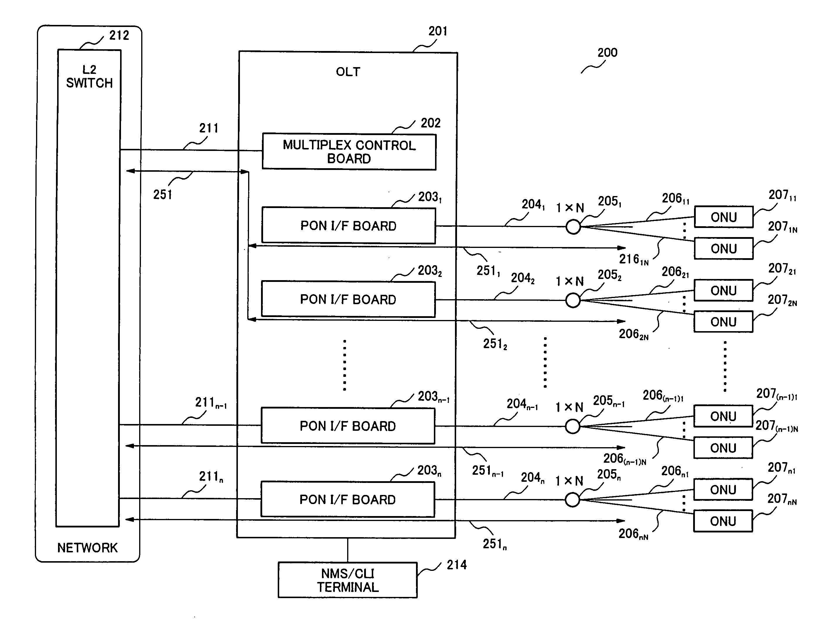
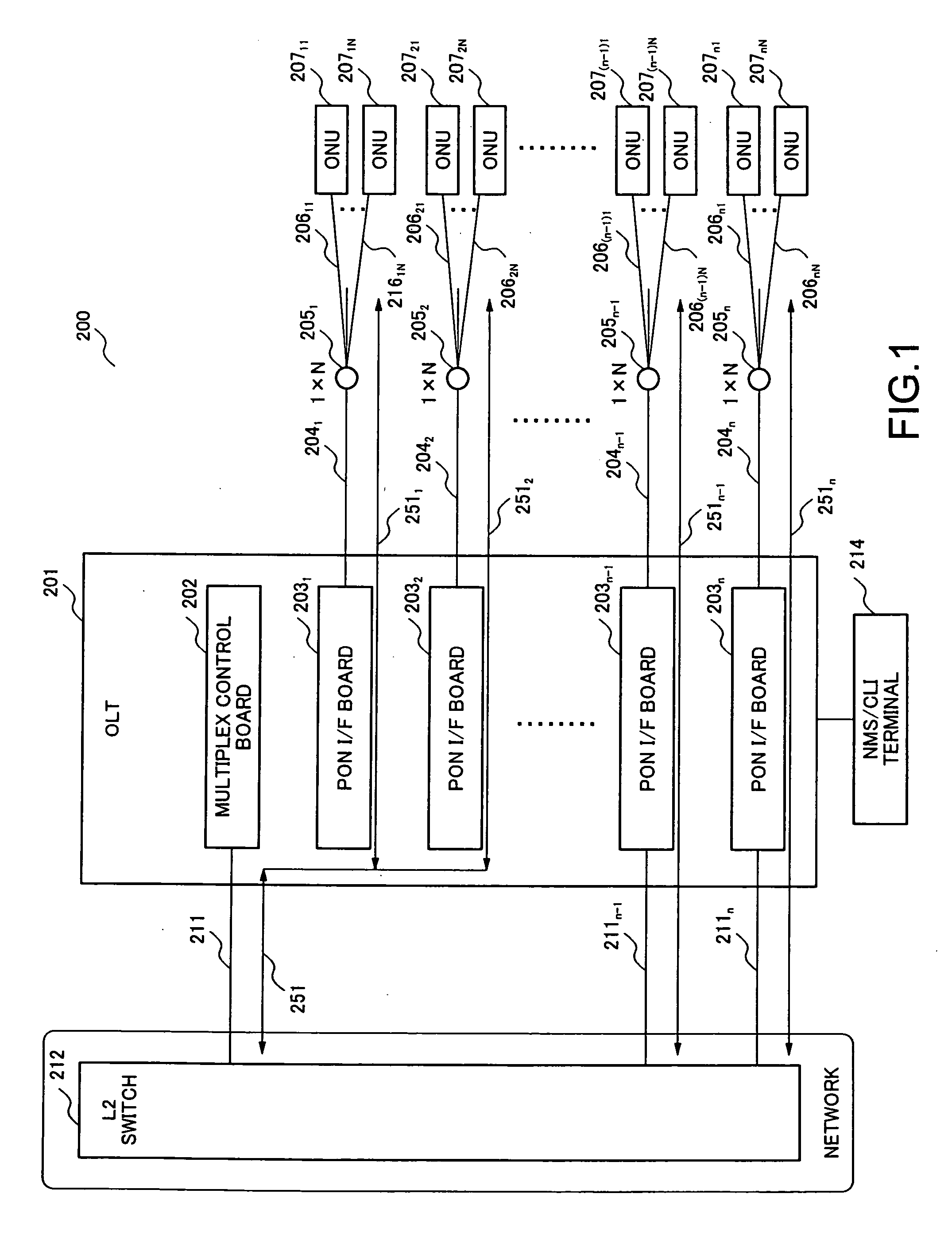
[0097]FIG. 6 is a system block diagram representing the essence of an optical access network according to a second embodiment of the present invention. In the optical access network 200A according to the second embodiment as shown in FIG. 6, the same parts are designated by the same reference numerals or signs as those of the optical access network 200 according to the first embodiment shown in FIG. 1, and the explanation of the same parts is omitted properly. In the optical access network 200A according to the second embodiment, contents of the path management tables of a multiplex control board 202A and each PON interface board 203A in an OLT 201A are slightly different from the path management tables of the multiplex control board 202 and each PON interface board 203 according to the first embodiment. Other points are the same as in the first embodiment.

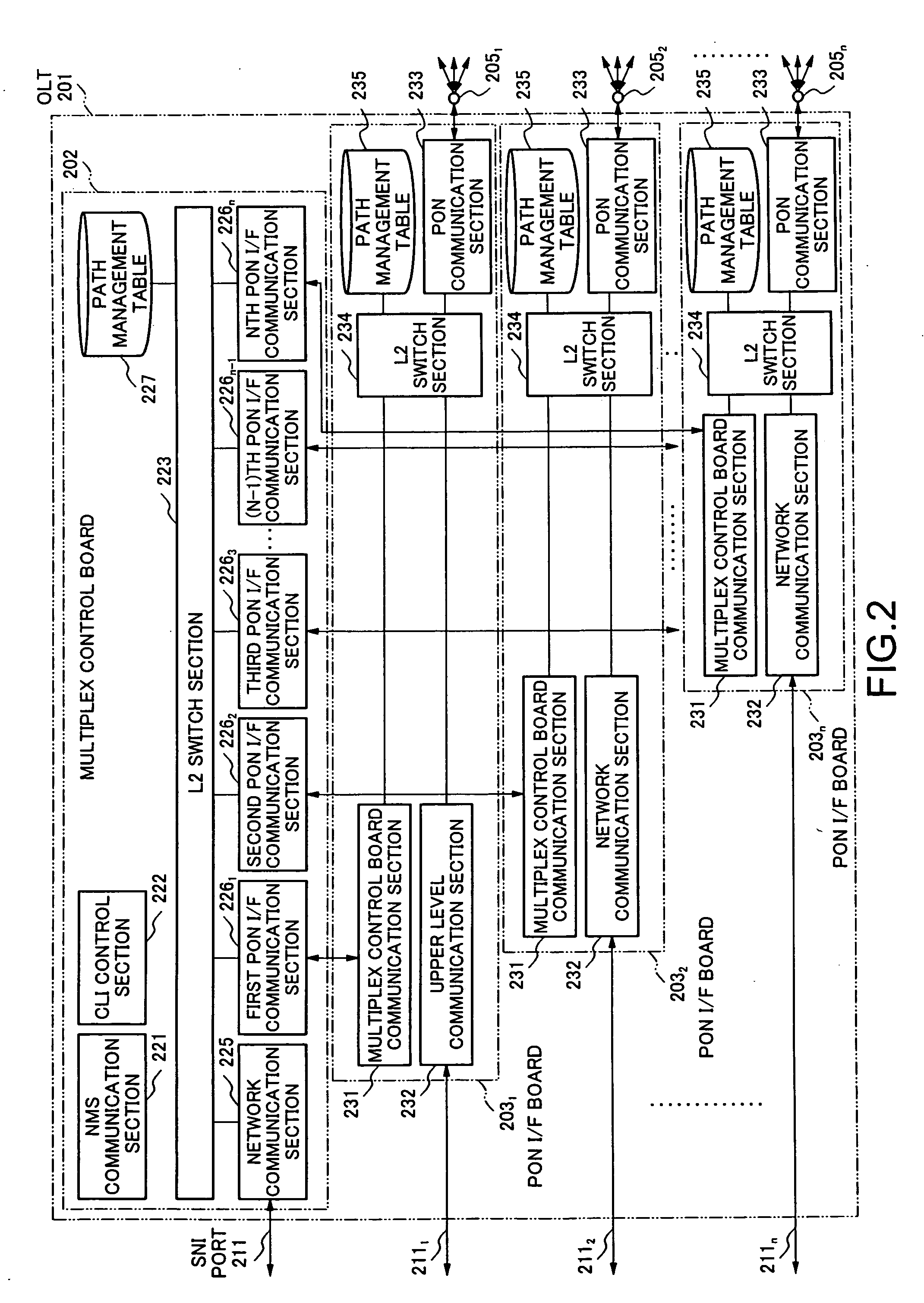
[0098]FIG. 7 is a block diagram representing the specific configuration of the OLT according to the sec...

exemplary embodiment 4

(Exemplary Embodiment 4)

[0145]FIG. 19 is a system block diagram representing the essence of an optical access network according to a fourth embodiment of the present invention. In the optical access network 200C according to the fourth embodiment as shown in FIG. 19, the same parts are designated by the same reference numerals or signs as in the optical access network 200 according to the first embodiment as shown in FIG. 1, and the explanation of the same parts is omitted properly. In the optical access network 200C according to the fourth embodiment, a multiplex control board 202C in an OLT 201C and n PON interface boards 2031C, 2032C, . . . and 203nC are slightly different from n PON interface boards 2031, 2032, . . . and 203n according to the first embodiment as shown in FIG. 1. Other points are the same as in the first embodiment.

[0146]FIG. 20 is a block diagram representing the specific configuration of the OLT 201C according to the fourth embodiment. The multiplex control bo...

exemplary embodiment 5

(Exemplary Embodiment 5)

[0158]FIG. 24 is a system block diagram representing the essence of an optical access network according to a fifth embodiment of the present invention. In the optical access network 200D according to the fifth embodiment as shown in FIG. 24, the same parts are designated by the same reference numerals or signs as in the optical access network 200 according to the first embodiment as shown in FIG. 1, and the explanation of the same parts is omitted properly. In the optical access network 200D according to the fifth embodiment, a multiplex control board 202D in an OLT 201D and n PON interface boards 2031D, 2032D, . . . and 203nD are slightly different from the multiplex control board 202 and n PON interface boards 2031, 2032, . . . and 203n according to the first embodiment. Other points are the same as in the first embodiment.

[0159]FIG. 25 is a block diagram representing the specific configuration of the OLT 201D according to this embodiment. In the fifth emb...


PUM


Abstract

The present invention realizes an Optical Line Terminal (OLT) in an optical access network and a data signal sending method for the optical access network in which the reliability of the network can be assured without increasing the cost of facility investment. The OLT comprises a multiplex control unit for providing a communication path to be used commonly for transmitting data signals for subscriber terminals to communicate with the network, a plurality of optical network interface units, each accommodates the subscriber terminals and provides either a first path connected to the network for transmitting the data signals individually or a second path connected to the multiplex control unit for transmitting the data signals to the network commonly with data signals from other subscriber terminals accommodated in other optical network interface unit, and a path selection control section, which determines for every optical network interface unit to select either the first path or the second path on the basis of path class information in a path management table in which respective path class information for every optical network interface unit have been predetermined and set.

Description

BACKGROUND OF THE PRESENT INVENTION [0001] 1. FIELD OF THE PRESENT INVENTION [0002] The present invention relates to an optical access network apparatus and its data signal sending method, and more particularly to an OLT (Optical Line Terminal) in an optical access network and a data signal sending method for enabling a subscriber terminal to send a data signal via the OLT to a network. [0003] 2. DESCRIPTION OF THE RELATED ART [0004] An xDSL (x-Digital Subscriber Line) is the generic term of ADSL (Asymmetric Digital Subscriber Line), HDSL (High-bit-rate DSL), RADSL (Rate-Adaptive DSL), SDSL (Symmetric DSL), and VDSL (Very-high-bit-rate DSL). This xDSL is a modem technique allowing for the fast packet communications at several tens Megabits / sec at maximum, using the existing subscriber line (ordinary telephone cable made of copper wire) as a transmission line. Due to the introduction of communication services employing the xDSL, a high-speed and always-connected internet access netwo...

Claims


Application Information

Patent Timeline
IPC IPC(8): H04J3/16H04L12/44
CPCH04J3/1694H04Q11/0066H04Q2011/0081H04Q2011/0073H04Q11/0067H04B10/00H04B10/27H04Q3/60
Inventor TANAKA, MASASHI
Owner NEC CORP
Why Eureka
Try Eureka