Method of effecting protection control in communication network and RPR apparatus

a technology of protection control and communication network, applied in multiplex communication, data switching network, instruments, etc., can solve the problems of rpr switch instability, long time-consuming and laborious switching, and so on

Inactive Publication Date: 2003-12-18
FUJITSU LTD
View PDF2 Cites 13 Cited by
  • Summary
  • Abstract
  • Description
  • Claims
  • Application Information

AI Technical Summary

Problems solved by technology

However, according to the above-described conventional technology, even if the RPR apparatus is equipped with a protection switching function which is highly reliable and capable of operating at a high speed, it takes a long period of time for switching from the network under current working status to the redundant network upon effecting the SONET protection function for failure restoration.
Further,

Method used


Image

  • Method of effecting protection control in communication network and RPR apparatus
  • Method of effecting protection control in communication network and RPR apparatus
  • Method of effecting protection control in communication network and RPR apparatus

Examples


first embodiment

[0046] [A-1] Description of Communication Network

[0047] FIG. 2 is a diagram showing a communication network to which the first embodiment of the present invention is applied. As shown in FIG. 2, the communication network is provided with RPR apparatus and SONET apparatus. The communication network is arranged so as to implement a protection control as a characteristic feature of the present invention which will be more fully described later on.

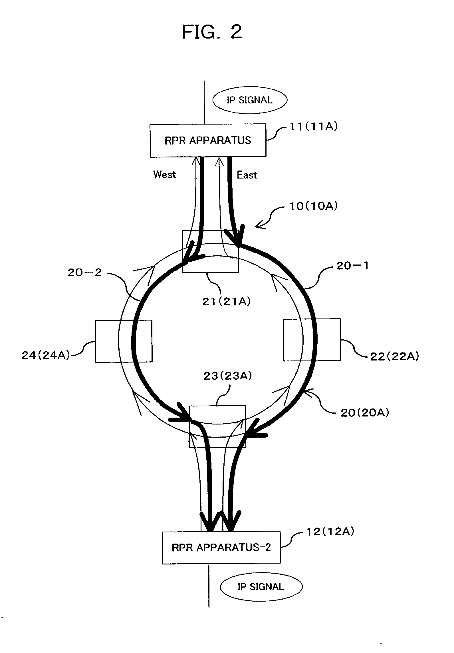
[0048] In FIG. 2, reference numeral 10 represents a resilient packet ring (RPR). This RPR 10 is composed of a couple of RPR apparatus 11, 12 connected to a bidirectional line-switched ring (BLSR) 20 which is formed of, for example, four synchronous optical network (SONET) apparatus 21 to 24 connected to one another through optical fibers so as to form a ring-like network.

[0049] In more concretely, the RPR apparatus 11 is connected to the SONET apparatus 21 and the RPR apparatus 12 is connected to the SONET apparatus 23. A signal transmitted fr...

second embodiment

[0134] [B] Description of Second Embodiment

[0135] FIG. 2 also shows an RPR 10A as a communication network according to a second embodiment of the present invention. As shown in FIG. 2, the RPR 10A includes a BLSR 20A connected with RPR apparatus 11A and 12A, similarly to the case of the aforesaid first embodiment. The BLSR 20A is arranged to include four SONET apparatus 21A to 24A connected to one another through optical fibers so as to form a ring-like network.

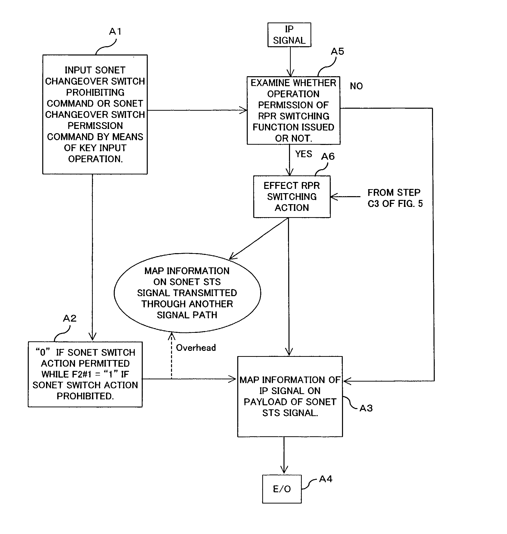
[0136] As described above, each of the resilient packet ring (RPR) and the synchronous optical network (SONET) is provided with a protection function that can be activated independently. However, the RPR 10A shown in FIG. 2 has the following particular control function. That is, similarly to that of the first embodiment, the network of the second embodiment can be placed in a mode in which the protection function of the BLSR can be activated. Under this condition, if any of the SONET apparatus 21A to 24A is brought into a swi...


PUM


Abstract

An object of the present invention is to propose a method of effecting a protection control for use in a communication network which makes it possible to avoid conflict between a protection switch of a SONET apparatus and a protection switch of an RPR apparatus. To this end, when ring switching of the BLSR is validated, the protection function of the RPR apparatus is invalidated while when the protection function of the RPR apparatus is validated, the ring switching of the BLSR is invalidated. The apparatus of the present invention can be applied to a network in which a ring network formed of a BLSR is connected with an RPR apparatus.

Description

[0001] 1. Field of the Invention[0002] The present invention relates to a method of effecting a protection control in a communication network and an RPR apparatus suitable for use in a communication network of an EOS (Ethernet Over SONET) in particular, in which a resilient packet ring (RPR) of the Ethernet (R) is placed upon a bidirectional line-switched ring (BLSR) composed of a plurality of synchronous optical network (SONET) apparatus, i.e., a ring network formed of the BLSR is connected with the RPR apparatus.[0003] 2. Description of the Related Art[0004] Recently, the Internet becomes more and more widely deployed in a communication field and with this trend, amount of communication information exchanged by means of IP (Internet Protocol) is remarkably increased. The IP communication is originally developed for data communication as a main object. Therefore, the IP communication has not been requested to have a high real time property as compared with a voice communication. Ac...

Claims


Application Information

Patent Timeline
IPC IPC(8): H04B10/032H04B10/07H04B10/27H04B10/275H04J3/14H04L12/437
CPCH04L12/437H04J3/14
Inventor KIMURA, GAKUISHIOKA, YUZURU
Owner FUJITSU LTD
Why Eureka
Try Eureka