Optical access network apparatus and data signal sending method therefor

a technology of optical access network and data signal, which is applied in the field of optical access network apparatus and its data signal sending method, can solve the problems of increasing the cost of facility investment, affecting the transmission characteristics and data transmission speed, and no system has been proposed for protecting a portion of the pon interface board. , to achieve the effect of improving convenience or ease of facility maintenance management, reducing the number of devices, and flexible setting

Active Publication Date: 2009-07-28
NEC CORP
View PDF6 Cites 15 Cited by
  • Summary
  • Abstract
  • Description
  • Claims
  • Application Information

AI Technical Summary

Benefits of technology

[0024]An exemplary feature of the present invention is to provide an Optical Line Terminal (OLT) in an optical access network and a data signal sending method for the optical access network in which the reliability of the network can be assured without increasing the cost of facility investment. It is another exemplary feature of the present invention to provide an OLT in an optical access network and a data signal sending method for the optical access network in which the data received from the subscriber terminal can be flexibly routed for each subscriber or each service.
[0026]According to the present invention, the data signal of the subscriber terminal is received via the PON interface, and the path management table is referred to, whereby when this data signal is transmitted to the network, it is possible to select a way of transmitting the data signal, i.e. concentrate or non-concentrate. That is, the path can be flexibly set by arranging the internal data of the OLT without depending on the physical topology between the subscriber and the network. Accordingly, the communication common carrier (or the network provider) can simplify the network path design for the optical access network to a network, whereby the convenience or easiness of the facility maintenance management is improved.

Problems solved by technology

However, as the xDSL technology involves the packet communication using the telephone cable, it has a problem that the transmission characteristics and the data transmission speed are affected by the length of the telephone cable, the characteristics of the telephone cable, and the peripheral environmental conditions of wiring path of the telephone cable from a telephone switching office to the subscriber's premises.
However, no system has been proposed yet for protecting a portion relating to the PON interface boards and the SNI ports at the time of fault.
A first problem is that the cost of facility investment is increased when redundant configuration facilities are provided for the network element of network side in the conventional optical access network of non-concentrate type.
Therefore, various facilities are required doubly by simply making the apparatus duplex, so that the cost of equipment is increased.
A second problem is that the conventional OLT 201 of concentrate type cannot separate the data traffic for transmission depending on the type of subscriber (or subscriber class).
However, the redundant configuration of the multiplex board will cause the complex settings of internal control and troublesome operation for quality assurance in assuring the quality of data depending on the subscriber class.
A third problem is that the degree of freedom of setting a path to the network for each subscriber or service is lowered in the both forms of the non-concentrate type and the concentrated type.

Method used


Image

  • Optical access network apparatus and data signal sending method therefor
  • Optical access network apparatus and data signal sending method therefor
  • Optical access network apparatus and data signal sending method therefor

Examples


exemplary embodiment 1

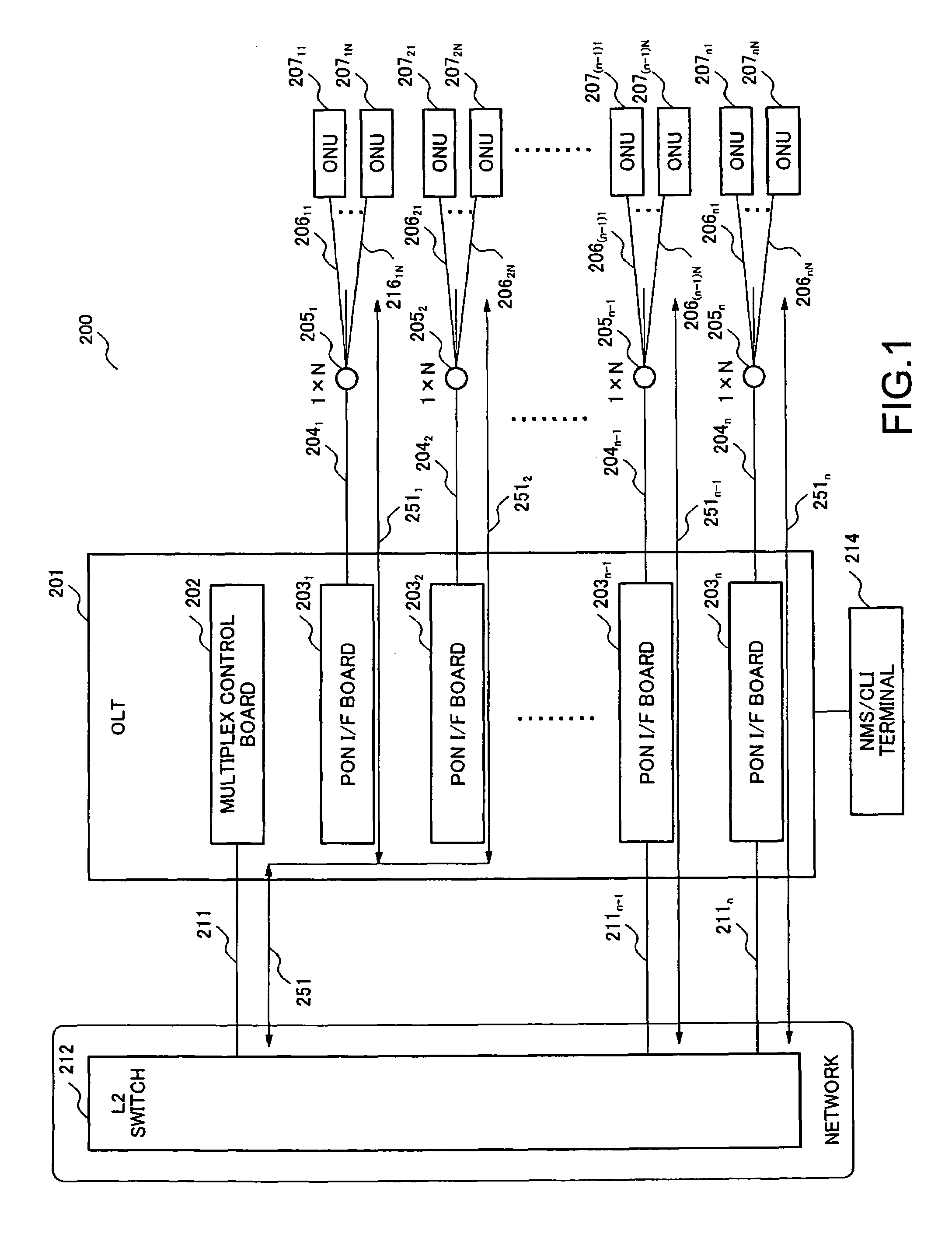
[0059]FIG. 1 is a system block diagram schematically representing the essence of an optical access network according to a first embodiment of the present invention. The optical access network 200 of this embodiment constitutes a GEPON (Gigabit Ethernet Passive Optical Network) system as an example.

[0060]In the optical access network 200 of this embodiment, an OLT 201 comprises a multiplex control board 202 and n (n is arbitrary integer) PON interface (I / F) boards 2031, 2032, . . . and 203n. One ends of the optical fiber cables 2041, 2042, . . . and 204n are correspondingly connected to the PON interface boards 2031, 2032, . . . and 203n, and the other ends of the optical fiber cables 2041, 2042, . . . and 204n are connected to the 1×N splitters 2051, 2052, . . . and 205n, and each optical fiber cable is split into N (N is arbitrary integer) optical fiber cables by the 1×N splitter. The split optical fiber cables 20611 to 2061N, 20621 to 2062N, . . . and 206n1 to 206nN are connected ...

exemplary embodiment 2

[0097]FIG. 6 is a system block diagram representing the essence of an optical access network according to a second embodiment of the present invention. In the optical access network 200A according to the second embodiment as shown in FIG. 6, the same parts are designated by the same reference numerals or signs as those of the optical access network 200 according to the first embodiment shown in FIG. 1, and the explanation of the same parts is omitted properly. In the optical access network 200A according to the second embodiment, contents of the path management tables of a multiplex control board 202A and each PON interface board 203A in an OLT 201A are slightly different from the path management tables of the multiplex control board 202 and each PON interface board 203 according to the first embodiment. Other points are the same as in the first embodiment.

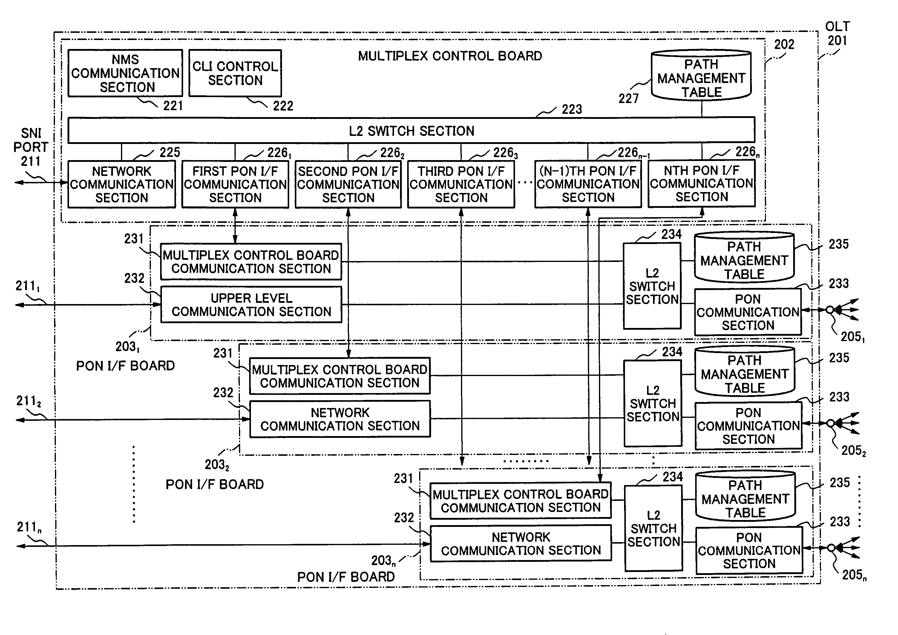
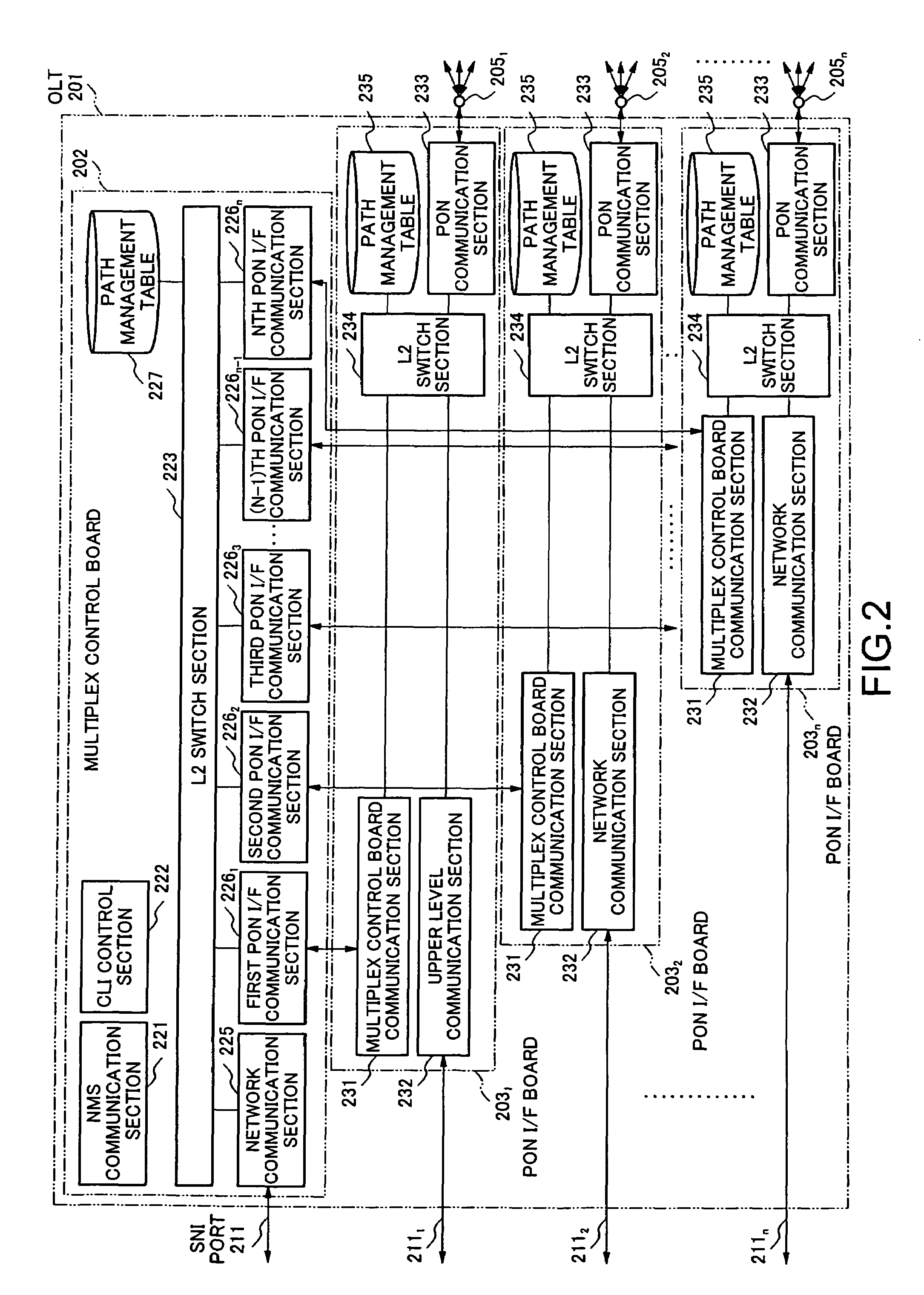
[0098]FIG. 7 is a block diagram representing the specific configuration of the OLT according to the second embodiment. The same ...

exemplary embodiment 3

[0108]FIG. 9 is a system block diagram representing the essence of an optical access network according to a third embodiment of the present invention. In the optical access network 200B according to the third embodiment as shown in FIG. 9, the same parts are designated by the same reference numerals or signs as those of the optical access network 200 according to the first embodiment as shown in FIG. 1, and the explanation of the same parts is omitted properly. The optical access network 200B according to the third embodiment is different from the optical access network 200 according to the first embodiment in that a multiplex control board 202B in an OLT 201B has a DHCP (Dynamic Host Configuration Protocol) server function, an IGMP (Internet Group Management Protocol) snooping function and an MLD (Multicast Listener Discovery) snooping function, and a path management table with a multiplex control board function valid policy is contained in each of the path management tables of the...


PUM


Abstract

The present invention realizes an Optical Line Terminal (OLT) in an optical access network and a data signal sending method for the optical access network in which the reliability of the network can be assured without increasing the cost of facility investment. The OLT comprises a multiplex control unit for providing a communication path to be used commonly for transmitting data signals for subscriber terminals to communicate with the network, a plurality of optical network interface units, each accommodates the subscriber terminals and provides either a first path connected to the network for transmitting the data signals individually or a second path connected to the multiplex control unit for transmitting the data signals to the network commonly with data signals from other subscriber terminals accommodated in other optical network interface unit, and a path selection control section, which determines for every optical network interface unit to select either the first path or the second path on the basis of path class information in a path management table in which respective path class information for every optical network interface unit have been predetermined and set.

Description

BACKGROUND OF THE PRESENT INVENTION[0001]1. Field of the Present Invention[0002]The present invention relates to an optical access network apparatus and its data signal sending method, and more particularly to an OLT (Optical Line Terminal) in an optical access network and a data signal sending method for enabling a subscriber terminal to send a data signal via the OLT to a network.[0003]2. Description of the Related Art[0004]An xDSL (x-Digital Subscriber Line) is the generic term of ADSL (Asymmetric Digital Subscriber Line), HDSL (High-bit-rate DSL), RADSL (Rate-Adaptive DSL), SDSL (Symmetric DSL), and VDSL (Very-high-bit-rate DSL). This xDSL is a modem technique allowing for the fast packet communications at several tens Megabits / sec at maximum, using the existing subscriber line (ordinary telephone cable made of copper wire) as a transmission line. Due to the introduction of communication services employing the xDSL, a high-speed and always-connected internet access network has b...

Claims


Application Information

Patent Timeline
Patent Type & Authority Patents(United States)
IPC IPC(8): H04L12/56H04J14/00H04J3/02H04L12/26H04L12/44
CPCH04J3/1694H04Q11/0067H04Q11/0066H04Q2011/0081H04Q2011/0073H04B10/00H04B10/27H04Q3/60
Inventor TANAKA, MASASHI
Owner NEC CORP
Why Eureka
Try Eureka