Braze assembly with beryllium diffusion barrier and method of making same

a technology of diffusion barrier and braze joint, which is applied in the field of x-ray tubes, can solve the problems of early life failure of x-ray tubes and weakening of braze joints

Active Publication Date: 2011-01-11
GENERAL ELECTRIC CO
View PDF7 Cites 6 Cited by
  • Summary
  • Abstract
  • Description
  • Claims
  • Application Information

AI Technical Summary

Problems solved by technology

However, diffusion and alloying between the fusible material and the parts being joined may result in formation of brittle intermetallic compounds, sometimes referred to as Laves phase intermetallics, which can weaken the braze joint and cause early life failure of the x-ray tube.

Method used


Image

  • Braze assembly with beryllium diffusion barrier and method of making same
  • Braze assembly with beryllium diffusion barrier and method of making same
  • Braze assembly with beryllium diffusion barrier and method of making same

Examples


Embodiment Construction

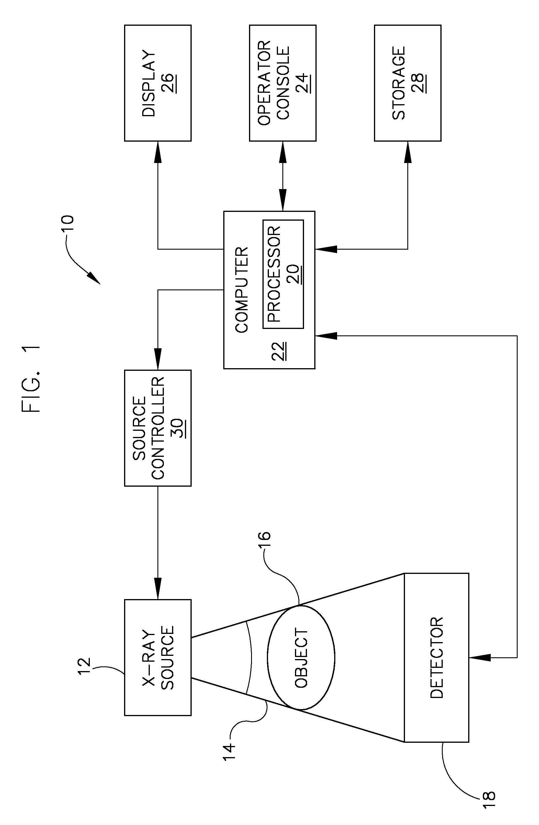
[0020]FIG. 1 is a block diagram of an embodiment of an imaging system 10 designed both to acquire original image data and to process the image data for display and / or analysis in accordance with the invention. It will be appreciated by those skilled in the art that the invention is applicable to numerous medical imaging systems implementing an x-ray tube, such as x-ray or mammography systems. Other imaging systems such as computed tomography (CT) systems and digital radiography (RAD) systems, which acquire image three dimensional data for a volume, also benefit from the invention. The following discussion of x-ray system 10 is merely an example of one such implementation and is not intended to be limiting in terms of modality.

[0021]As shown in FIG. 1, x-ray system 10 includes an x-ray source 12 configured to project a beam of x-rays 14 through an object 16. Object 16 may include a human subject, pieces of baggage, or other objects desired to be scanned. X-ray source 12 may be a conv...


PUM

PropertyMeasurementUnit
melting pointaaaaaaaaaa
liquidus temperatureaaaaaaaaaa

Abstract

A bonded assembly includes a member, and a substrate comprising beryllium, the substrate configured to be bonded to the member. The bonded assembly includes a first barrier applied to a surface of the substrate, a second barrier applied to a surface of the first barrier, a bonding material disposed between the second barrier and the member, and wherein the second barrier is configured to prevent dissolution of the first barrier into the bonding material.

Description

BACKGROUND OF THE INVENTION[0001]The invention relates generally to x-ray tubes and, more particularly, to a method and apparatus for creating an improved braze in x-ray tube components.[0002]X-ray systems typically include an x-ray tube, a detector, and a gantry to support the x-ray tube and the detector. In operation, an imaging table, on which an object is positioned, is located between the x-ray tube and the detector. The x-ray tube typically emits radiation, such as x-rays, toward the object. The radiation typically passes through the object on the imaging table and impinges on the detector. As radiation passes through the object, internal structures of the object cause spatial variances in the radiation received at the detector. The detector then processes the received data, and the system translates the radiation variances into an image, which may be used to evaluate the internal structure of the object. One skilled in the art will recognize that the object may include, but i...

Claims


Application Information

Patent Timeline
Patent Type & Authority Patents(United States)
IPC IPC(8): G21K1/00B23K1/19
CPCC25D5/10H01J35/18Y10T428/12729H01J2235/18H01J2235/166
Inventor STEINLAGE, GREGORY ALANTIEARNEY, THOMAS C.ALLEN, DONALD ROBERT
Owner GENERAL ELECTRIC CO
Why Eureka
Try Eureka