
Enterprise management system

a management system and enterprise technology, applied in the field of network management, can solve problems such as errors or potential failures, achieve the effects of enhancing availability and robustness, reducing performance bottlenecks, and eliminating or reducing performance bottlenecks

Inactive Publication Date: 2011-01-18
MICROSOFT TECH LICENSING LLC
View PDF18 Cites 47 Cited by
  • Summary
  • Abstract
  • Description
  • Claims
  • Application Information

AI Technical Summary

Benefits of technology

[0011]Thus, one advantage of the present invention is that, by distributing management components, it eliminates or reduces performance bottlenecks, single point of failure issues, and allows independent network scaling.
[0012]Another advantage of the present invention is that, by facilitating communication among distributed manager components and self assignment of managing tasks by such components in the event of a detected failure, the management system achieves enhanced availability and robustness.
[0013]Another advantage of the present invention is that, because the basic monitored unit (managed element) may be a logical or software component as well as a physical component, the system can provide more detailed, intelligent information relating to failure events or potential failure events.
[0014]Another advantage of the present invention is that it provides an automated audit storage component, thus providing further useful information relating to events potentially leading to problems.
[0015]Other advantages of the present invention will become apparent from the more detailed description below.

Problems solved by technology

The managed network elements assume one of a set of predefined states, thus indicating an error or the potential for failure arising from a managed element.

Method used


Image

  • Enterprise management system
  • Enterprise management system
  • Enterprise management system

Examples


example

[1310]

Current State is Running3Children state is Warning2Propagation policy is WarningMin 2= Published state2Current State is Running2Children state is Warning1Propagation policy is WarningMin 2= Published state2Current State is Running3Children state is Warning3Propagation policy is WarningMin 2= Published state3

[1311]Note that the paused state is treated as the same as running when calculating the current statue of a ME.

Resource Policy

[1312]An ME can be configured to handle multiple ME's of the same type and which are viewed as a set of resources. Redundant resources are configured when the State Tracking component is receives input relating to how many resources must be running for the resource to be healthy. Additional the State Tracking component should be told what is the lowest level of redundant resources allowable before am ME becomes critical. Any value in between will cause the ME to publish a warning state.

[1313]For example, assuming there are 6 redundant services and 5 ...


PUM


Abstract

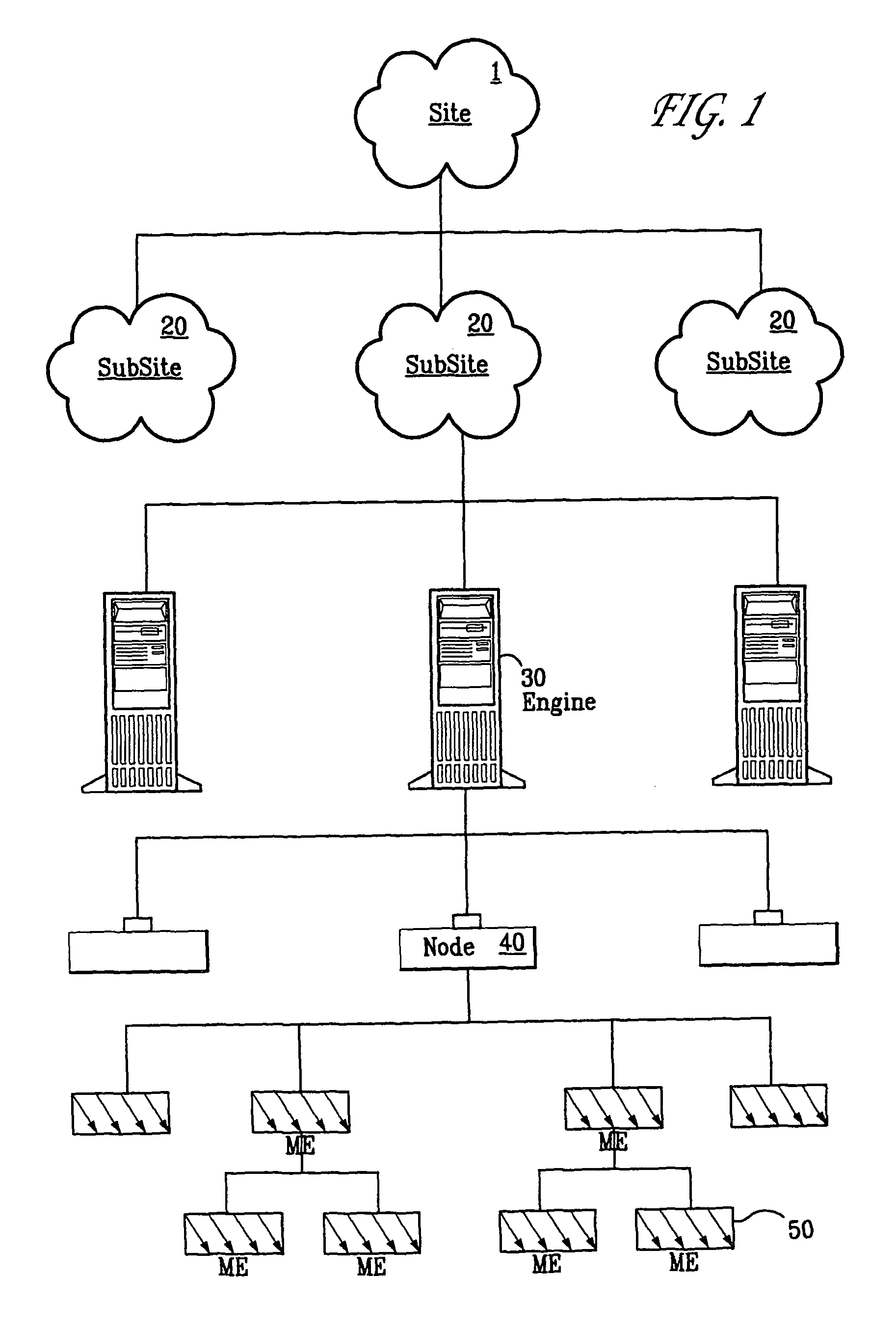
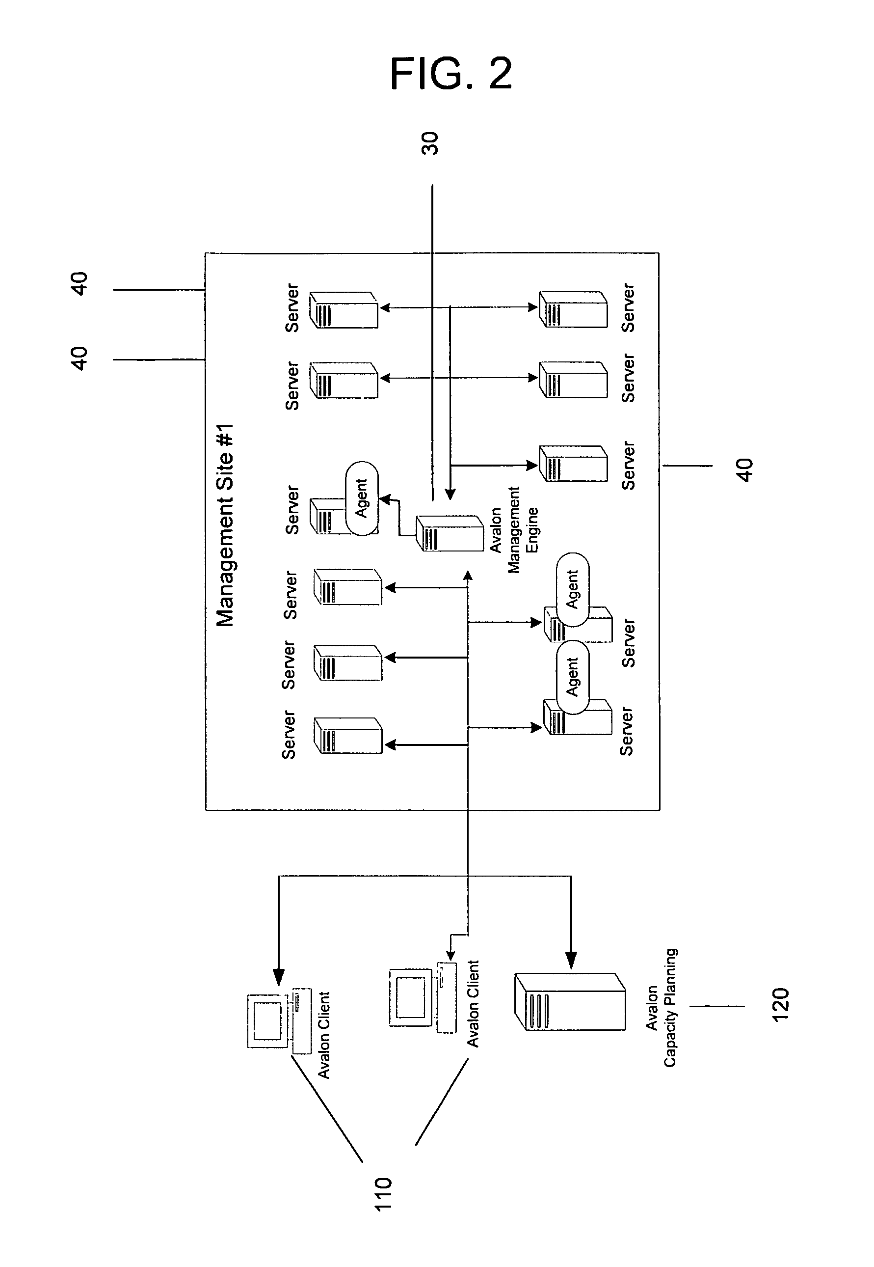
A Managed Site (10), a logical network entity, is composed of a number of Sub Sites (20) in a one to many relationship. A Sub Site (20) is a logical component, which is composed of a number of Engines (30). Nodes (40) similarly relates to their Engine (30) in a many to one relationship. A Node (40) is a collection of Managed Elements (ME's) (50) (while being an ME (50) itself), which represent network state information. The subsite (20) consists of the engine (30) connected to server nodes (40). One or more clients (110) are connected to the management engine (30) and access management engine (30) information relating to managed elements (50) including nodes (40). The connected manager engines may communicate with one another so that, for example, in the event of a failure, one of the manager engines remaining on line commences monitoring of manage elements assigned to the failed manager engine. Upon accessing the manager engine (30), the client interface displays relationships among managed elements (50) using meaningful connectors and tree-like structures. In addition to basic managed element state monitoring functionality, the manager engine (30) provides a variety of automated tasks ensuring the health of the network and optimal failure correction in the event of a problem. For example, the manager engine (30) performs root cause analysis utilizing an algorithm tracing through managed element (50) relationships and indicating the source of the failure.

Description

RELATED APPLICATIONS[0001]This application is a divisional of U.S. application Ser. No. 09 / 586,740, filed Jun. 5, 2000 now U.S. Pat. No. 6,983,317, entitled “Enterprise Management System” which claims the benefit of U.S. Provisional Application Ser. No. 60 / 206,014, filed May 19, 2000, entitled “Enterprise Management System” and U.S. Provisional Application Ser. No. 60 / 185,443, filed Feb. 28, 2000, entitled “Enterprise Management System.” The contents of the above referenced applications are hereby incorporated by reference.TECHNICAL FIELD[0002]The present invention relates generally to the field of network management, and more particularly to an elegant system and method for monitoring and controlling large, growing and complex networks.BACKGROUND OF THE INVENTION[0003]With the use of networks and networking burgeoning, numerous applications requiring communications and access to remote data are being performed more efficiently and in an enhanced manner. Following this trend, many e...

Claims


Application Information

Patent Timeline
Patent Type & Authority Patents(United States)
IPC IPC(8): G06F15/173
CPCH04L41/065H04L41/069H04L43/0811H04L41/0213H04L41/0253H04L41/046H04L41/0806H04L41/0893H04L41/0895H04L41/0894
Inventor BISHOP, DAVID A.HOOVER, KELVIN M.
Owner MICROSOFT TECH LICENSING LLC
Learn More