Powering disk drive spinup

a technology of powering disk drives and spinning platters, which is applied in the direction of motor/generator/converter stoppers, dynamo-electric converter control, instruments, etc., can solve the problems of large electrical power consumption, large power consumption of mechanical devices such as motors, and constant spinning of the platters in the hard disk drive, so as to save and make available data communication quickly and efficiently. , the effect of saving significant amounts of power and expens

Active Publication Date: 2011-01-18
EMC IP HLDG CO LLC
View PDF5 Cites 22 Cited by
  • Summary
  • Abstract
  • Description
  • Claims
  • Application Information

AI Technical Summary

Benefits of technology

[0015]Disk drives can be made available for data communication quickly and efficiently without excessive use of power. Data centers can save significant amounts of power and expense with little or no adverse affect on performance.

Problems solved by technology

Constantly spinning the platter in the hard disk drive consumes a large amount of power.
Powering a mechanical device, such as a motor, consumes a significant amount of power relative to the power consumed by the electronic circuitry within the system.
The consumption of electrical power is a major concern in many environments.
For example, in data centers, computing equipment such as storage systems cause power consumption not only directly but also indirectly, because cooling equipment such as air conditioners are required to remove the heat given off by the computing equipment (and in at least some cases, since cooling equipment is not 100% efficient, the indirect consumption exceeds the direct consumption).
In another example, power consumption is a major factor in the design and construction of portable computers.
At least some of the concern over power consumption relating to portable computers arises due to their reliance upon batteries with a short life, e.g., batteries with a short life due to limited energy storage capacity.
It is too expensive to provide a power subsystem that can support enough peak power to spin up many disk drives at once, especially when the excess power is not otherwise needed.
Some types of disk drives offer a separate HDA power input but no built in control over the timing of the application of power to the HDA.
Some other types offer limited control.
However, it is difficult for system software to use SCSI commands to control drive spin up timing, because insert and power control signals from the drives are asserted much faster than software can respond.
The ALPA address method is also disadvantageous in at least some circumstances.
But because its spin up timing depends on its ALPA address, it will nonetheless take several minutes to spin up.

Method used


Image

  • Powering disk drive spinup
  • Powering disk drive spinup
  • Powering disk drive spinup

Examples


Embodiment Construction

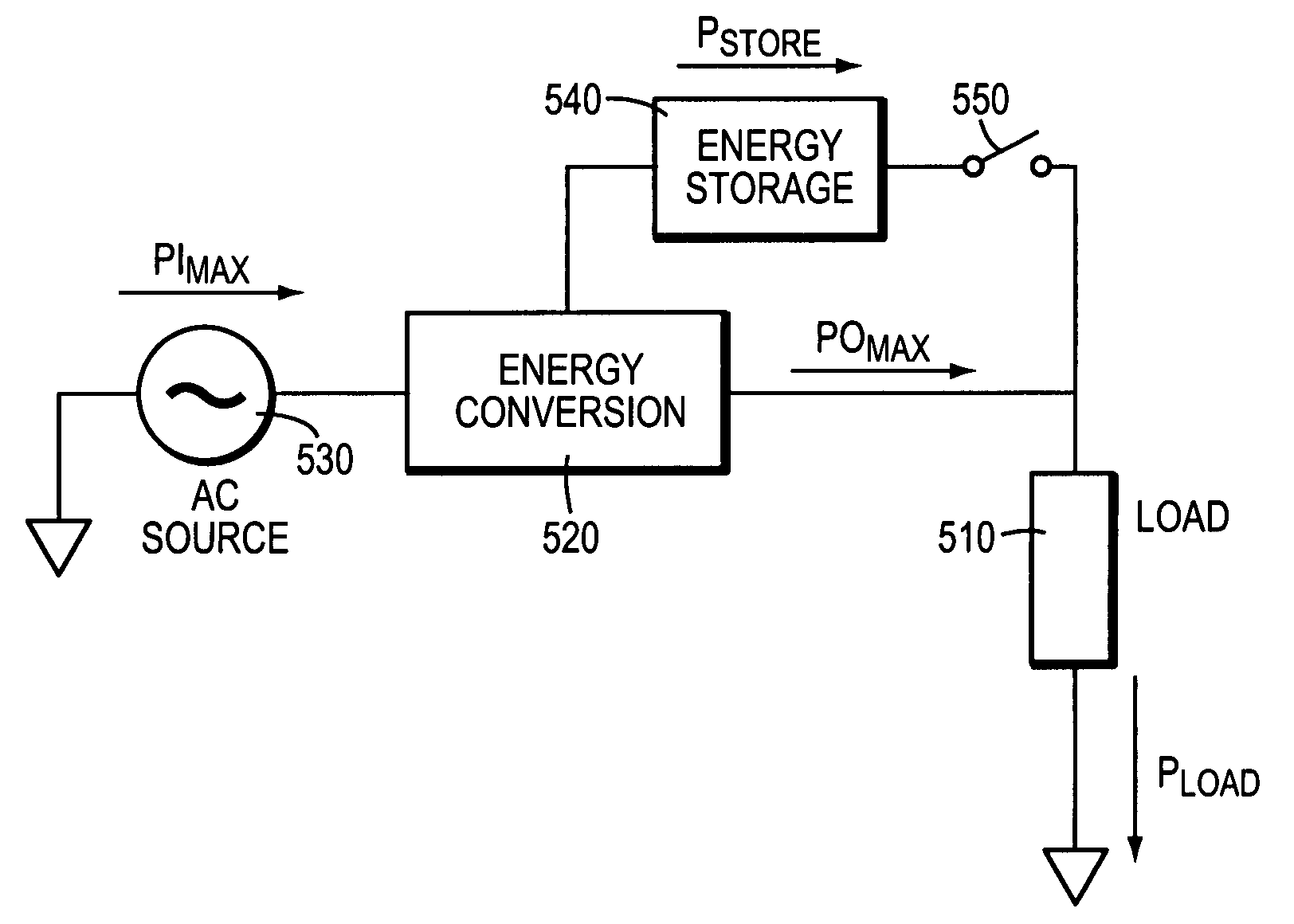
[0021]Described below is a technique for use in powering disk drive spinup. In at least some implementations, the technique reduces data-access times for powered down (“spun-down”) or slow-spin array states, and enables a system to provide fast recovery times from slow-spinning or spun-down rotating storage media by which power is saved during periods of inactivity.

[0022]Preferably, to minimize or nearly minimize the time to access the data, all disks in a spun-down or slow-spinning state that are required to service the request are spun up simultaneously. However, this takes additional energy, i.e., a short term energy surge, and conventionally in large system configurations, or in large data centers with multiple systems, this surge may not be available from the power distribution network. For example, a test of one typical disk drive revealed that spinning up drew approximately an extra 1.5 amps of current from a 12 volt DC power source for the duration of spin up, approximately ...


PUM

PropertyMeasurementUnit
power consumptionaaaaaaaaaa
poweraaaaaaaaaa
energyaaaaaaaaaa

Abstract

A method is used in powering disk drive spinup. A disk drive is powered with a primary power source and is temporarily powered with a secondary power source in addition to the primary power source. The secondary power source powers the disk drive when the disk drive is spinning up.

Description

BACKGROUND OF THE INVENTION[0001]The need for high performance, high capacity information technology systems is driven by several factors. In many industries, critical information technology applications require outstanding levels of service. At the same time, the world is experiencing an information explosion as more and more users demand timely access to a huge and steadily growing mass of data including high quality multimedia content. The users also demand that information technology solutions protect data and perform under harsh conditions with minimal data loss. And computing systems of all types are not only accommodating more data but are also becoming more and more interconnected, raising the amounts of data exchanged at a geometric rate.[0002]Thus, today's data storage systems are used in computing environments for generating and storing large amounts of critical data. Some storage systems support many (e.g., hundreds) of disk drives. A hard disk drive is typically a devic...

Claims


Application Information

Patent Timeline
Patent Type & Authority Patents(United States)
IPC IPC(8): G06F1/00G06F11/00H02K29/08G11B11/00G06F12/00H02P6/00
CPCG06F1/3221G06F1/3268G11B19/2054G11B19/2072Y02B60/1246Y02D10/00
Inventor LINNELL, THOMAS E.ROUX, PHILLIP J.
Owner EMC IP HLDG CO LLC
Why Eureka
Try Eureka