Segmented annular combustor

a combustor and annular technology, applied in the direction of combustion process, hot gas positive displacement engine plant, combustion process, etc., can solve the problems of increased mechanical and thermal loads on the walls surrounding the combustion chamber and other components, affecting the combustion process of one burner and the combustion process of the other burner, and increasing noise production

Inactive Publication Date: 2011-01-25
SIEMENS ENERGY INC
View PDF18 Cites 32 Cited by
  • Summary
  • Abstract
  • Description
  • Claims
  • Application Information

AI Technical Summary

Problems solved by technology

Consequently, combustion processes in one burner may affect the combustion processes in the other burners.
Combustion oscillations can cause an increased production of noise and may also increase mechanical and thermal loads on walls surrounding the combustion chamber and on other components in and around the combustion section.
In modern engines, temperatures in the combustion section have increased to increase the output power of the engine, thus exacerbating the problems associated with combustion oscillations.
However, it would be desirable to design a non-can-annular system that could be tuned on an individual basis such that thermoacoustic problems could be predicted by testing only a portion of the system.

Method used


Image

  • Segmented annular combustor
  • Segmented annular combustor
  • Segmented annular combustor

Examples


Embodiment Construction

In the following detailed description of the preferred embodiments, reference is made to the accompanying drawings that form a part hereof, and in which is shown by way of illustration, and not by way of limitation, specific preferred embodiments in which the invention may be practiced. It is to be understood that other embodiments may be utilized and that changes may be made without departing from the spirit and scope of the present invention.

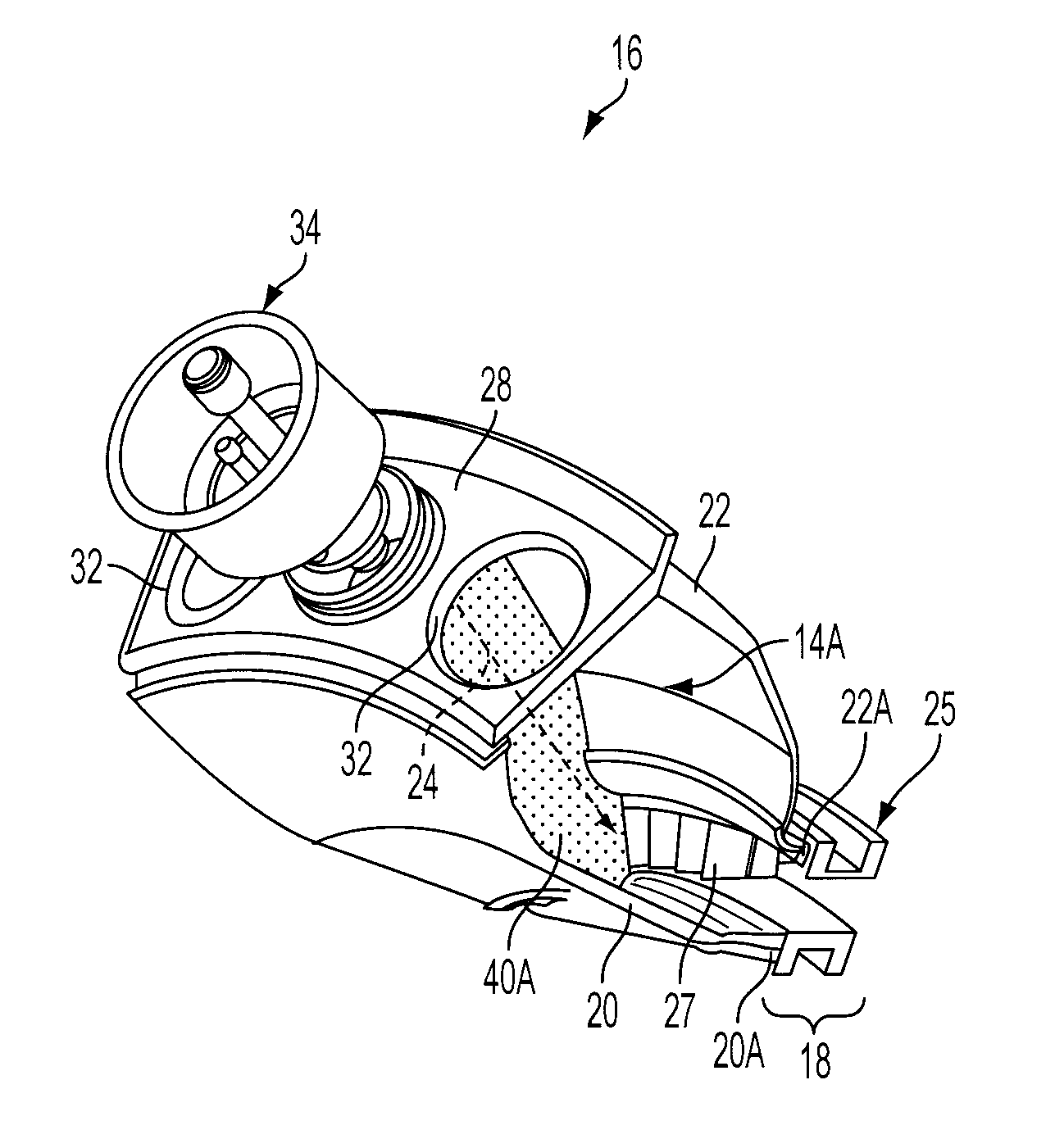
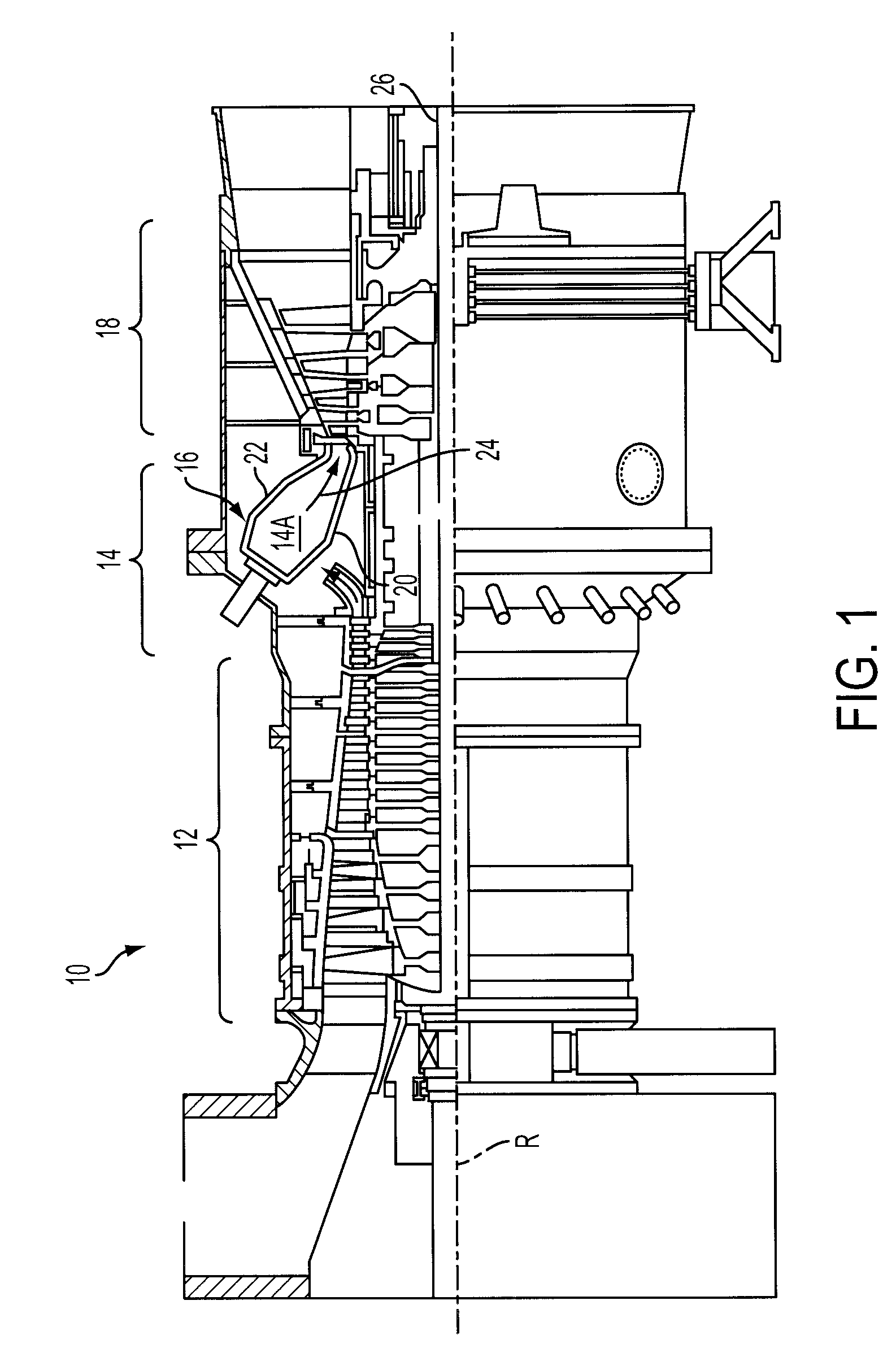
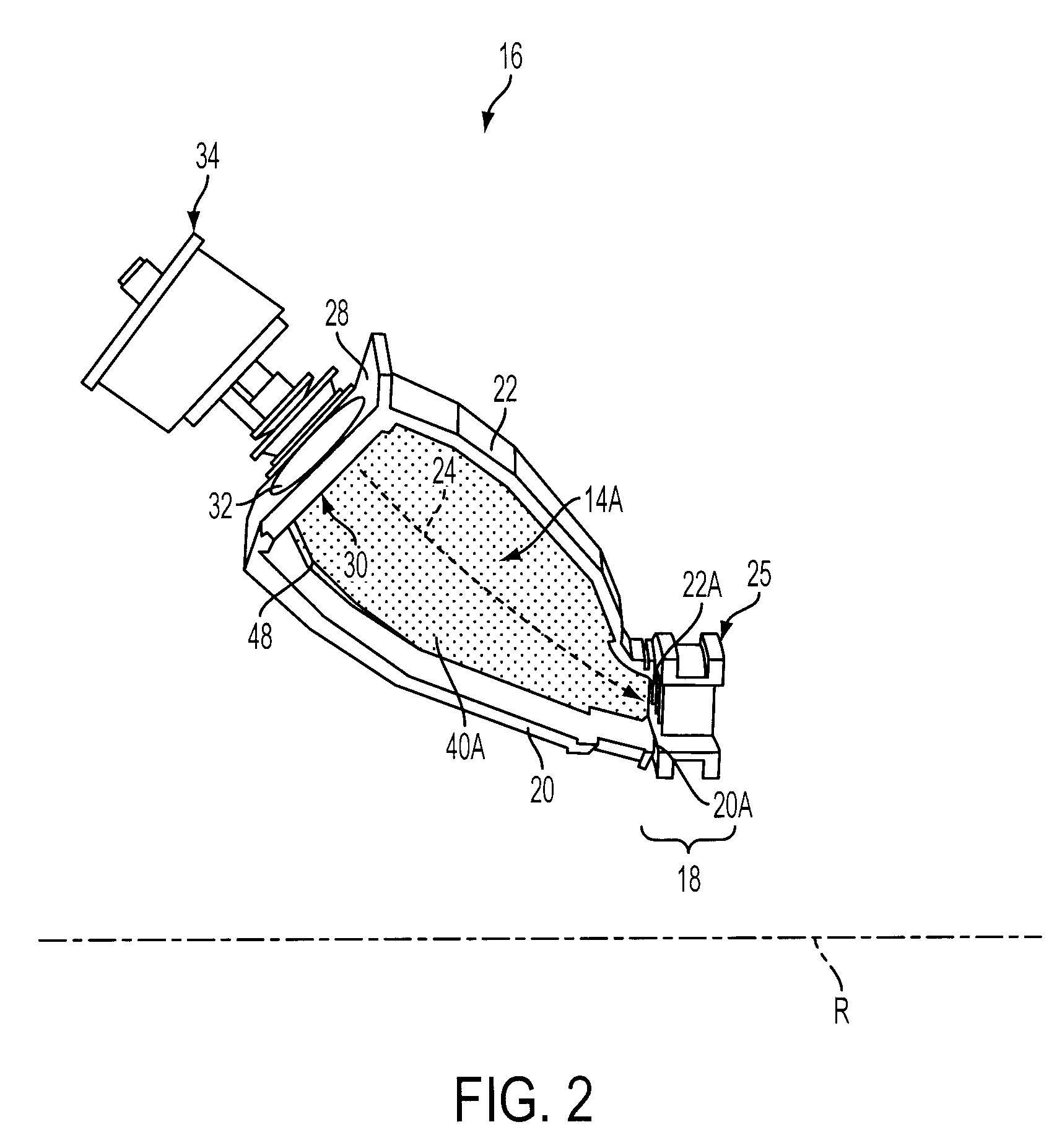
Referring to FIG. 1, a gas turbine engine 10 is shown. The engine 10 includes a compressor section 12, a combustion section 14 including an annular combustor 16, and a turbine section 18. The compressor section 12 inducts and pressurizes inlet air which is directed to the combustor 16 in the combustion section 14. Upon entering the combustor 16, the compressed air from the compressor section 12 is mixed with a fuel and ignited in a main combustion zone 14A defined between an inner annulus wall 20 and an outer annulus wall 22 disposed radially ...


PUM


Abstract

A combustor for use in a turbine engine including a compressor section, a combustion section downstream from the compressor section, and a turbine section downstream from the combustion section. An inner annulus wall extends from a burner end of the combustor to an outlet end of the combustor. An outer annulus wall is disposed outwardly from the inner annulus wall and extends from the burner end of the combustor to the outlet end of the combustor. A passageway is formed between the inner annulus wall and the outer annulus wall and extends from a combustion zone to the outlet end of the combustor. A plurality of symmetrically distributed section walls extends between the inner annulus wall and the outer annulus wall from the burner end of the combustor toward the outlet end of the combustor. The section walls divide the combustion zone into a plurality of segments.

Description

FIELD OF THE INVENTIONThe present invention relates to an annular combustor for use in a turbine engine, and more particularly, to an annular combustor including a plurality of section walls that operate to reduce combustion oscillations.BACKGROUND OF THE INVENTIONIn gas turbine engines, compressed air discharged from a compressor section and fuel introduced from a source of fuel are mixed together and burned in a combustion section. The mixture is directed through a turbine section, where the mixture expands to provide rotation of a turbine rotor. The turbine rotor may be linked to an electric generator, wherein the rotation of the turbine rotor can be used to produce electricity in the generator.Gas turbine engines using annular combustion systems typically include a plurality of individual burners or fuel nozzles disposed in a ring about an axial centerline for providing a mixture of fuel and air to an annular combustion chamber disposed upstream of the turbine section of the eng...

Claims


Application Information

Patent Timeline
Patent Type & Authority Patents(United States)
IPC IPC(8): F02C3/00
CPCF23M9/06F23R3/002F23R3/16F23R3/42F23R3/50
Inventor RUBIO, MARK B.RITLAND, DAVID M.
Owner SIEMENS ENERGY INC
Why Eureka
Try Eureka