Powered surgical instruments

a surgical instrument and power technology, applied in the field of powered surgical instruments, can solve the problems of complicated procedures, damage or breakage of alveolar bones, and unsatisfactory procedures

Inactive Publication Date: 2011-01-25
WESTPORT MEDICAL
View PDF34 Cites 16 Cited by
  • Summary
  • Abstract
  • Description
  • Claims
  • Application Information

AI Technical Summary

Problems solved by technology

While the rocking technique allows a dental professional to remove a tooth, the procedure is not ideal.
Additionally, the limited space in the mouth in which the dental professional must complete this rocking technique complicates the procedure.
Furthermore, in some circumstances, the rocking motion can be applied with too much force damaging the crown of the tooth before the socket is sufficiently expanded or resulting in damage or breaks in the alveolar bone.
Further, broken alveolar bone may complicate the installation of a dental implant immediately after extraction, sometimes requiring bone grafts and subsequent implant placement at a later date.
The rocking procedure briefly described above may be difficult to perform when there is little or no crown for the dental professional to grip.
For example, in some patients, the crown may be sufficiently deteriorated, or not sufficiently extended above the alveolar bone to enable a dental professional to grip the crown.
Drilling the bone may result in undesired bone removal.
The pain and potential complications associated with the bone graft procedure and the delay in installation of the implant may be undesirable for both the patient and the dental professional.
A great amount of force may be required to use the manual periotome and the dental professional's hand and arm may be fatigued by the process.
More than just inconvenient, the use of several different instruments may be expensive for the dental professional.

Method used


Image

  • Powered surgical instruments
  • Powered surgical instruments
  • Powered surgical instruments

Examples


Embodiment Construction

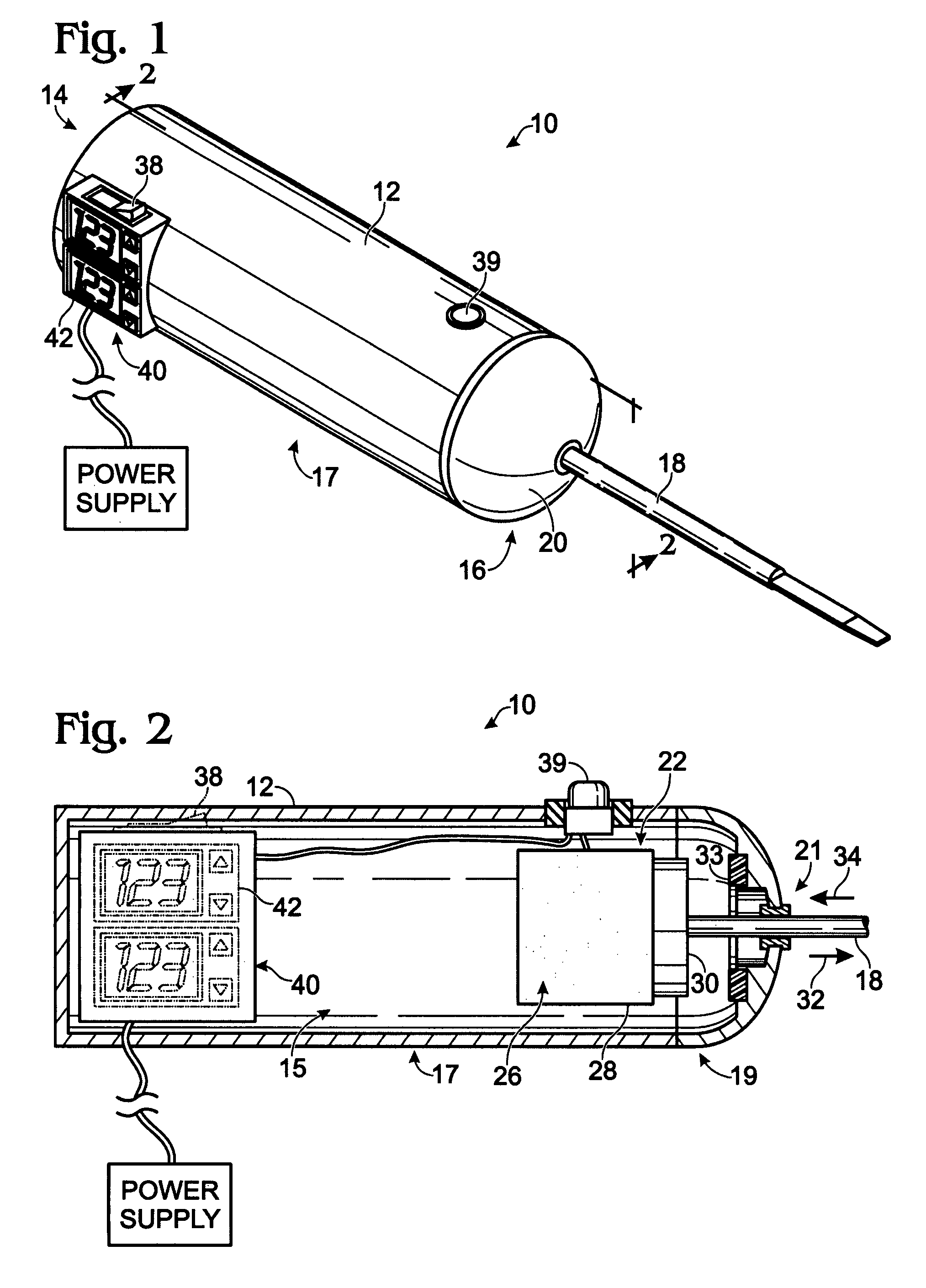
[0033]FIG. 1 illustrates, somewhat schematically, a perspective view of a powered surgical instrument according to one embodiment of the present disclosure. The powered surgical instrument described below may be used in any suitable dental or medical application, including, for example, extraction of teeth and dental implant procedures. Further, such powered surgical instrument may be used in both human medical and dental applications, as well as veterinary medical and dental applications.

[0034]The drawings depict a plurality of embodiments for the powered surgical instrument and reference characters may refer to corresponding elements throughout multiple views. Similarly, the drawings are intended to show illustrative embodiments that depict a variety of elements and subelements. The elements and / or subelements described may be selectively embodied in devices according to the present disclosure alone or in combination with one or more other elements and / or subelements, regardless o...


PUM


Abstract

A powered surgical instrument is provided. In some embodiments, the powered surgical instrument may include a housing; a receiver, at least a portion of the receiver is movably received within the housing, a distal end portion of the receiver being configured to receive an expander adapted to expand a tooth socket within a treatment area, wherein the receiver is configured to move between a first receiver position and a second receiver position; a bias assembly operatively connected to the receiver and configured to urge the receiver towards the second receiver position; and an actuator disposed within the housing and configured to move the receiver at least from the first receiver position to the second receiver position, wherein the receiver is configured to be selectively moved between the first and second receiver positions independent of the actuator.

Description

CROSS-REFERENCE TO RELATED APPLICATIONS[0001]This application is a continuation-in-part of U.S. patent application Ser. No. 10 / 890,711, filed Jul. 13, 2004 now abandoned and entitled “Powered Surgical Instrument.” The complete disclosure of that application is herein incorporated by reference for all purposes.BACKGROUND OF DISCLOSURE[0002]A tooth may need to be extracted from the mouth for a variety of reasons. For example, in some situations it may be desirable to extract a tooth that is decayed, damaged or loose. Other times, teeth may be extracted for ‘orthodontic’ reasons, such as to provide room for other teeth, enable other teeth to grow, etc.[0003]In its most basic form, a tooth includes a crown, which is the upper, visible portion of the tooth, and a root structure, which is hidden from view in the boney substructure of alveolar bone comprising the socket. A tooth is secured in place by a combination of factors, including the structural relationship between the root structur...

Claims


Application Information

Patent Timeline
Patent Type & Authority Patents(United States)
IPC IPC(8): A61C1/07
CPCA61C1/0007A61C1/07A61C1/148A61C3/03A61C8/0089A61C1/0023A61C1/0038A61C3/14
Inventor BOUNEFF, ANTHONY B.
Owner WESTPORT MEDICAL
Why Eureka
Try Eureka