Electromagnetic switching device

a switching device and electromagnetic technology, applied in the direction of contact mechanism, contact details, contact vibration/shock damping, etc., can solve the problem that the vibration generated in the electromagnetic device is not easily transmitted to the case, and achieve the effect of increasing the resistance to vibration, reducing manufacturing costs, and increasing connection strength

Active Publication Date: 2011-01-25
MATSUSHITA ELECTRIC WORKS LTD
View PDF55 Cites 43 Cited by
  • Summary
  • Abstract
  • Description
  • Claims
  • Application Information

AI Technical Summary

Benefits of technology

[0009]In the electromagnetic switching device of the present invention, because the electromagnetic device is supported by the case through the cushioning member, the vibration generated in the electromagnetic device is not transmitted to the case directly, and it is absorbed by the cushioning member. Therefore, the vibration generated in the electromagnetic device is not easily transmitted to the case, whereby it is possible to reduce the vibration to be transmitted from the electromagnetic device to the case. Furthermore, because the flange of the coil bobbin is away from the movable core and the fixed core, which are the source of the impact, it is possible to reduce the impact to be transmitted from the electromagnetic device to the case more by supporting such a flange by the case.
[0041]The connecting member may be formed integrally with the coil terminal. In this case, it is possible to reduce the number of parts.

Problems solved by technology

Therefore, the vibration generated in the electromagnetic device is not easily transmitted to the case, whereby it is possible to reduce the vibration to be transmitted from the electromagnetic device to the case.

Method used


Image

  • Electromagnetic switching device
  • Electromagnetic switching device
  • Electromagnetic switching device

Examples


Embodiment Construction

[0105]Hereinafter, the present invention will be described in more detail with reference to the accompanying drawings.

[0106]In an embodiment below, although an encapsulated electromagnetic switching device, in which a contact device, a fixed core, and a movable core are housed in an airtight space, will be explained, the present invention can be applied to an electromagnetic switching device in which a contact device, a fixed core, and a movable core are not housed in a airtight space, of course.

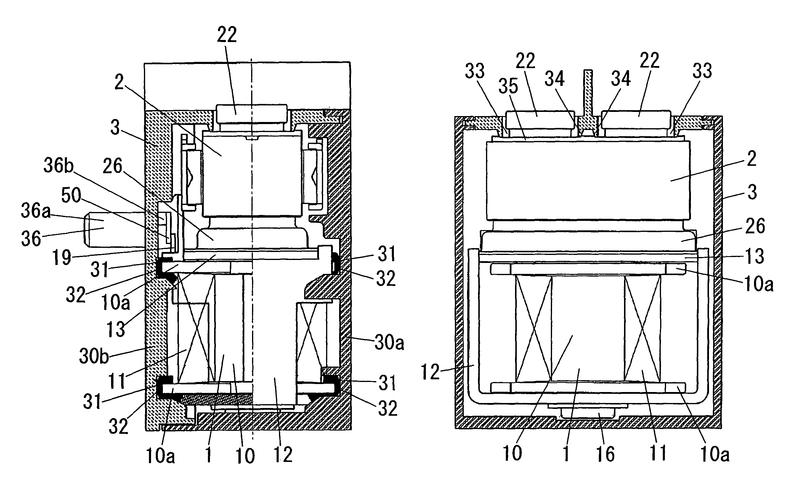
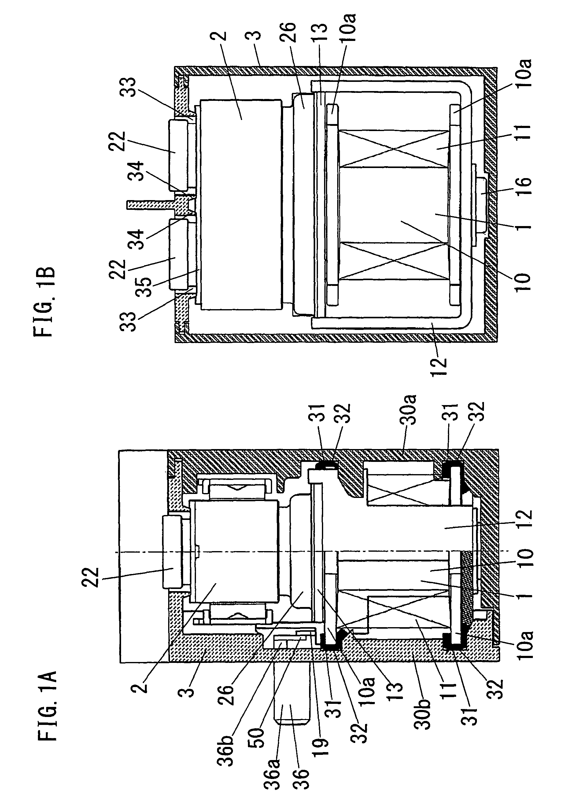
[0107]As shown in FIGS. 1A and 1B, the electromagnetic switching device of this embodiment has an electromagnetic device 1, a contact device 2 which opens and closes contacts in conjunction with the movement of the electromagnetic device 1, and a case 3 for housing the electromagnetic device 1 and the contact device 2.

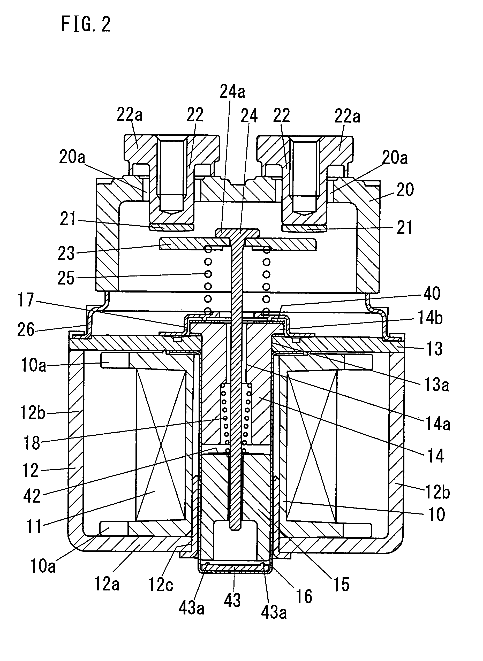
[0108]As shown in FIG. 2, the electromagnetic device 1 comprises a cylindrical coil bobbin 10, an excitation coil 11 wound around the coil bobbin 10, a generally U-shaped yoke ...


PUM


Abstract

This electromagnetic switching device comprises an electromagnetic device 1 in which a movable core 15 comes into contact with or separates from a fixed core 14 in response to energization of an excitation coil 11 wound around a coil bobbin 10 a contact device 2 with a fixed contact 21 and a movable contact which comes into contact with or separates from the fixed contact in conjunction with a movement of the movable core 15 of the electromagnetic device, and a boxy case 3 configured to house the electromagnetic device and the contact device. The coil bobbin 10 has a flange 10a at its end in an axis direction of the coil bobbin, and the case 3 has, on its inner surface, a recess 31 into which a periphery of the flange 10a of the coil bobbin is fitted, and a cushioning member 32 for absorbing an impact which is transmitted from the electromagnetic device to the case is disposed in the recess, and the flange of the coil bobbin is supported by the recess through the cushioning member whereby the electromagnetic device is supported in the case.

Description

TECHNICAL FIELD[0001]The present invention relates to an electromagnetic switching device having, in a case, an electromagnetic device and a contact device which opens and closes between contacts in conjunction with the motion of the electromagnetic device.BACKGROUND ART[0002]Japanese Non-examined Patent Publication No. 11-232986 discloses an electromagnetic switching device having an electromagnetic device and a contact device in a case.[0003]The electromagnetic switching device comprises an electromagnetic device in which a movable core comes into contact with or separates from a fixed core in response to energization of an excitation coil wound around a coil bobbin, a contact device with a fixed contact and a movable contact which comes into contact with or separates from the fixed contact in conjunction with the movement of the movable core of the electromagnetic device, and a boxy case for housing the electromagnetic device and the contact device. The movable contact is support...

Claims


Application Information

Patent Timeline
Patent Type & Authority Patents(United States)
IPC IPC(8): H01H67/02
CPCH01H50/04H01H50/30H01H50/443H01H50/44H01H50/54
Inventor URUMA, KATSUYAITOU, MASAHIROKUBO, MOTOHARUYAMAMOTO, RITSUUOTOME, RIICHI
Owner MATSUSHITA ELECTRIC WORKS LTD
Why Eureka
Try Eureka