Liquid crystal display apparatus

a technology of liquid crystal display and display plate, which is applied in the direction of lighting and heating apparatus, instruments, light sources, etc., can solve the problems of difficulty in assembling, difficulty in assembling, and difficulty in assembling, so as to achieve the effect of less susceptible to variations and easy assembly

Inactive Publication Date: 2011-01-25
FUNAI ELECTRIC CO LTD
View PDF8 Cites 8 Cited by
  • Summary
  • Abstract
  • Description
  • Claims
  • Application Information

AI Technical Summary

Benefits of technology

It is an object of the present invention to provide a liquid crystal display apparatus in which a reflection sheet, a diffusion plate, and a diffusion sheet can be disposed at accurate respective positions quickly when arranged, and accordingly, which is easy to assemble, and is less susceptible to occurrence of variations due to an assembly error.
It is another object of the present invention to provide a liquid crystal display apparatus in which a reflection sheet, a diffusion plate, and a diffusion sheet can be disposed at prescribed respective positions with accuracy, and the respective members can be controlled to the minimum necessary dimensions, and accordingly, which can reduce the manufacturing cost.
It is a still other object of the present invention to provide a liquid crystal display apparatus in which a reflection sheet, a diffusion plate, and a diffusion sheet can be prevented from being mounted in a displaced or distorted manner, and other members than the respective members can be mounted with ease and quickly.
With this configuration, it is possible to mount the diffusion plate at a prescribed mounting position with accuracy without using a specific member or using a specific method. This can reduce the occurrence of variations in display performance of the liquid crystal display apparatus due to the assembly error during manufacturing.
With this configuration, it is possible to dispose the reflection sheet at a prescribed position of the rear frame with accuracy without using a fixing method such as adhesion. By disposing the reflection sheet at an accurate position, it is possible to enhance the reflection efficiency. In addition, it is possible to prevent the reflection sheet from becoming an obstacle when the members to be mounted on the rear frame such as a backlight and a light frame are disposed.

Problems solved by technology

Thus, problems may occur in terms of structure or (and) performance due to variations in operation.
Therefore, holes must be opened in all the optical sheets, which takes time and effort.
Thus, manufacturing of the light guide plate and the liquid crystal display panel takes time and effort.
Whereas, provision of the projections results in the complicated shape, which complicates the manner in which a force is exerted thereon.
As a result, a stress may concentrate on an unexpected site, leading to breakage.

Method used


Image

  • Liquid crystal display apparatus
  • Liquid crystal display apparatus
  • Liquid crystal display apparatus

Examples


Embodiment Construction

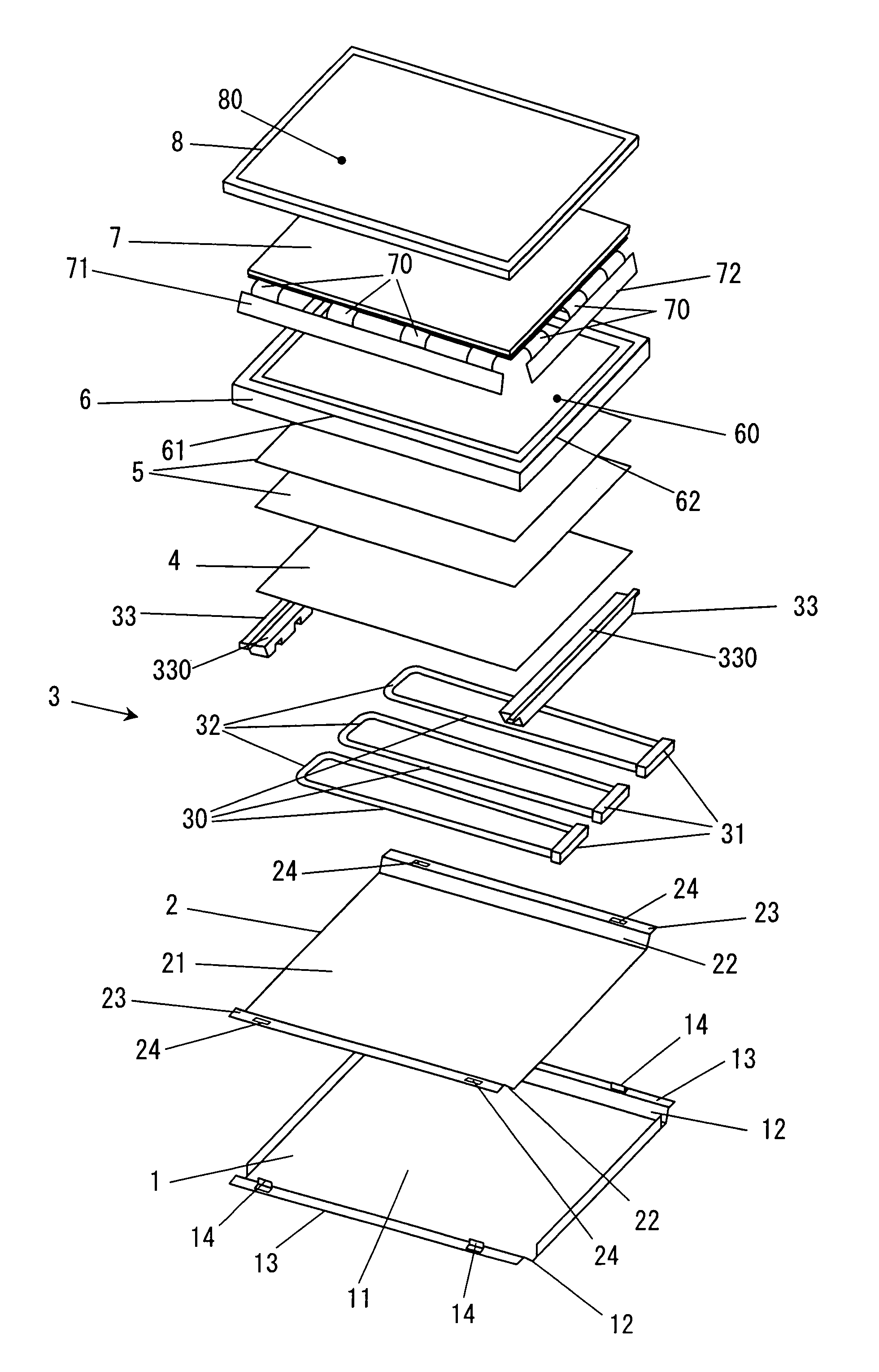
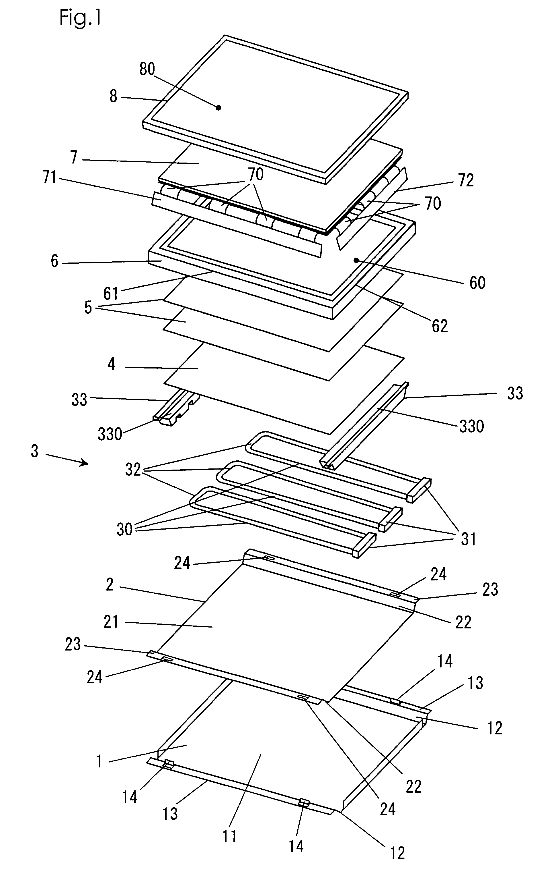
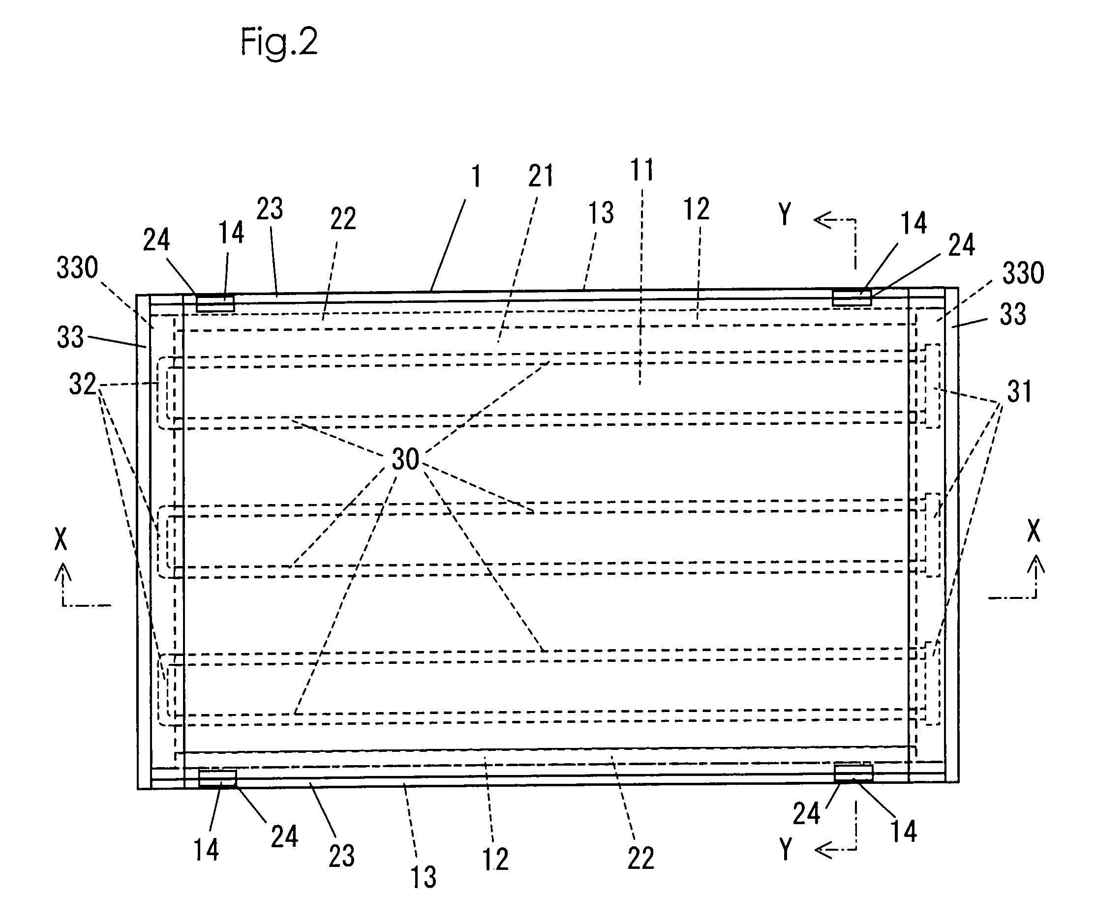
Below, the present invention will be described by way of embodiments by reference to the accompanying drawings. FIG. 1 is an exploded perspective view of one example of a liquid crystal display apparatus in accordance with the present invention; FIG. 2 is a plan view of the liquid crystal display apparatus shown in FIG. 1; FIG. 3 is a cross sectional view of the liquid crystal display apparatus shown in FIG. 2 cut along cross section X-X; and FIG. 4 is a cross sectional view of the liquid crystal display apparatus shown in FIG. 2 cut along cross section Y-Y. In FIG. 2 to FIG. 4, a cell guide, a liquid crystal cell, and a bezel are not shown for convenience. The liquid crystal display apparatus shown in FIG. 1 includes a rear frame 1, a reflection sheet 2, a backlight 3, a diffusion plate 4, a diffusion sheet 5, a cell guide 6, a liquid crystal cell 7, and a bezel 8 stacked in this order.

The rear frame 1 is formed by cutting and bending a metal plate. The rear frame 1 has a bottom su...


PUM

PropertyMeasurementUnit
transparentaaaaaaaaaa
adhesionaaaaaaaaaa
structureaaaaaaaaaa

Abstract

A liquid crystal display apparatus is configured such that protrusions penetrate through the through holes of the fitting portions of a reflection sheet, and such that each short side of a diffusion plate and a diffusion sheet stacked on the diffusion plate fits with the step portion of a light frame, and each long side thereof is in contact with the protrusion.

Description

This application is based on Japanese Patent Application No. 2006-301818 filed on Nov. 7, 2006, the contents of which are hereby incorporated by reference.BACKGROUND OF THE INVENTION1. Field of the InventionThe present invention relates to a liquid crystal display apparatus. More particularly, it relates to a mounting structure of an optical member such as a reflection sheet, a diffusion sheet, or a diffusion plate.2. Description of Related ArtA liquid crystal display apparatus is of a thin type, is lightweight, and is low in power consumption, and is widely used for a notebook PC, a monitor for PC, a household TV set, or the like. The liquid crystal display apparatus transmits a light emitted from a backlight through a liquid crystal cell to form a picture. The liquid crystal display apparatus includes optical members such as a reflection sheet for reflecting a light emitted from the backlight, a diffusion plate for diffusing a light emitted from the backlight and a light reflected...

Claims


Application Information

Patent Timeline
Patent Type & Authority Patents(United States)
IPC IPC(8): G02F1/1333G02F1/1335F21Y103/37
CPCG02F1/133308G02F1/133608G02F1/133604G02F1/133606G02F2001/133322G02F1/133322
Inventor FUKUDA, YUTAKA
Owner FUNAI ELECTRIC CO LTD
Why Eureka
Try Eureka