Measurement of round trip latency in write and read paths
What is AI technical title?
AI technical title is built by Patsnap AI team. It summarizes the technical point description of the patent document.
a technology of applied in the field of measurement of round trip latency in write and read path, can solve the problems of temperature sensitive and voltage sensitive, and the latency is due in part, and achieve the effects of accurate determination of write clock phase, accurate estimation of round trip latency, and increased target position accuracy
Inactive Publication Date: 2011-01-25
SEAGATE TECH LLC
View PDF7 Cites 14 Cited by
Summary
Abstract
Description
Claims
Application Information
AI Technical Summary
This helps you quickly interpret patents by identifying the three key elements:
Problems solved by technology
Method used
Benefits of technology
Benefits of technology
[0017]The invention further provides a method for accurately determining write clock phase for positioning a write transducer in a hard disk drive. This method includes: estimating round trip latency in a write-read path that includes driving a square wave onto a write data line to the write-read path and sensing a returned signal at a read channel input; a phase shift assembly that is adapted to generate a delayed signal being a second square wave delayed by a predetermined amount; a mixer that mixes the return signal and the delayed signal; cancelling cross talk from the returned signal; determining a phase shift that relates to the latency of the round trip from which a latency estimation is determined from a phase shift that is in quadrature with the returned signal, and using the latency estimation in an associated write clock phase determination for increasing accuracy of a targeted position for write operations.
Problems solved by technology
Many storage systems and communication systems experience latencies in the electronics or other portions of the system.
Many of the electronics in the read and write electronics, such as the preamplifier chip, are highly temperature sensitive and voltage sensitive.
These are also impacted by environmental conditions.
Thus, the latency is due in part to the latency of the electronics, which vary with temperature, voltage and environmental conditions.
Method used
Image
Click on the blue label to locate the original text in one second.
Reading with bidirectional positioning of images and text.
Examples
Embodiment Construction
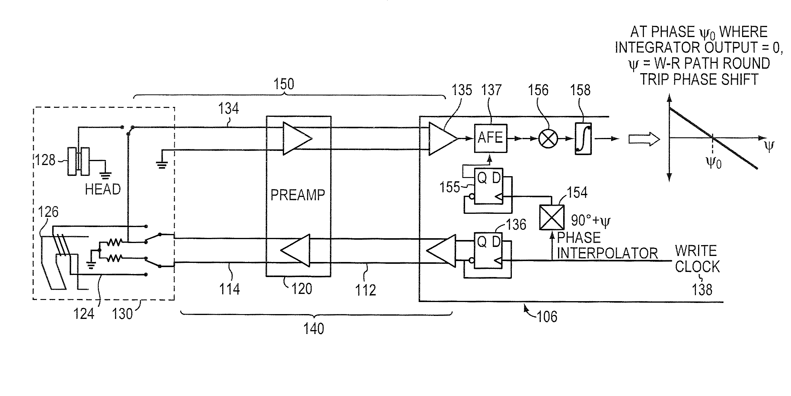
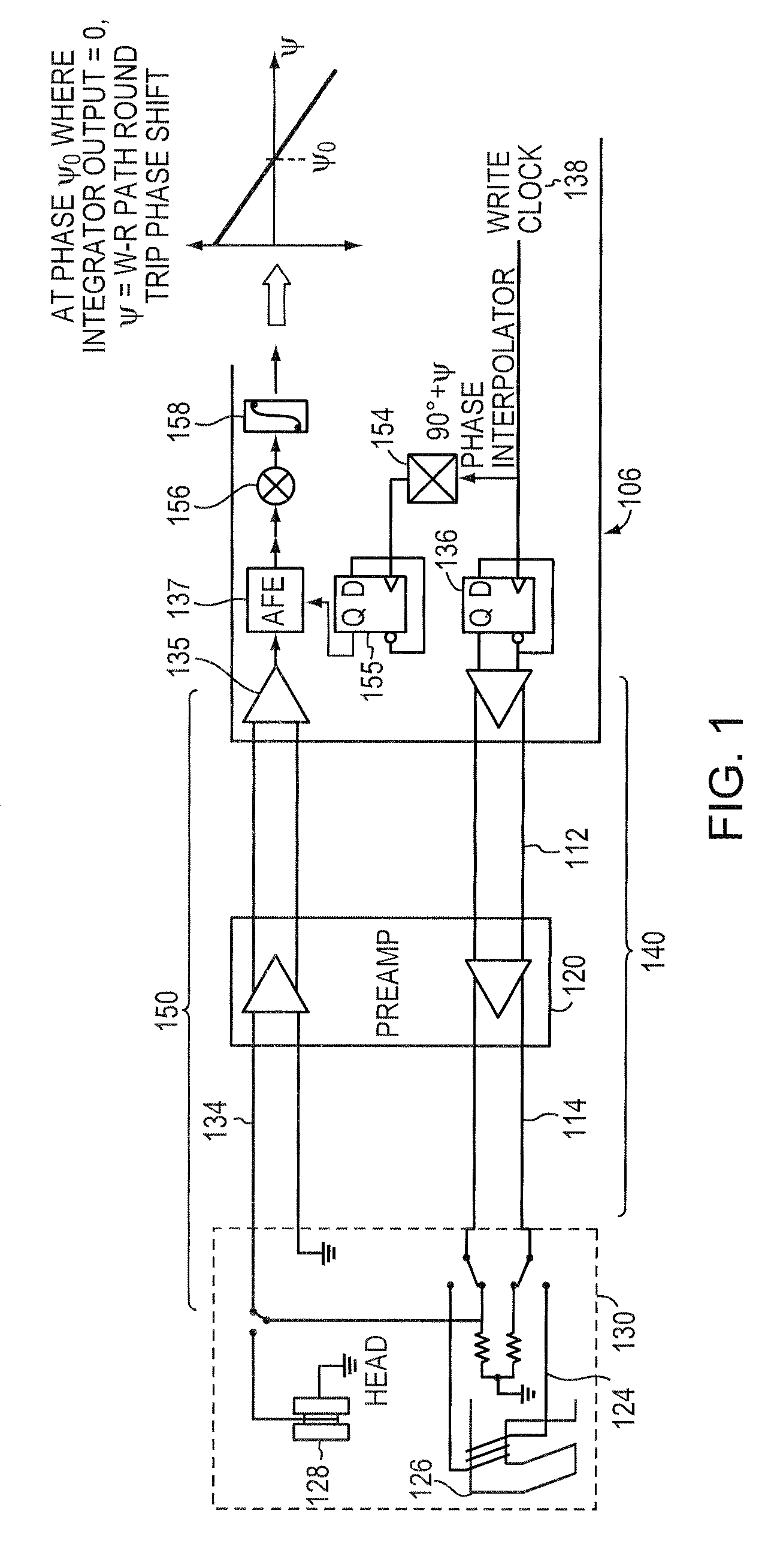
[0025]FIG. 1 is a schematic block diagram of a system 100 for estimating the phase shift that corresponds to round trip write-read path latency, in accordance with an illustrative embodiment of the present invention. The system 100 is a hard disk drive that typically includes a hard disk drive (HDD) controller, and a read channel circuit, which includes a phase estimation circuit 106 in which the techniques of the present invention are implemented.
[0026]Briefly, and by way of further background the HDD controller is a suitable microprocessor and accompanying electronics which are configured to receive I / O inputs from a user or a computer for either writing data or requesting files stored on the disks which are served by the hard disk drive. In a write operation, the HDD controller generates a channel write gate signal and passes this write gate signal to the read channel electronic circuit. Additionally, a second write gate signal is generated by the HDD controller and transmitted t...
PUM
Property
Measurement
Unit
phase shift
aaaaa
aaaaa
phase
aaaaa
aaaaa
phases
aaaaa
aaaaa
Abstract
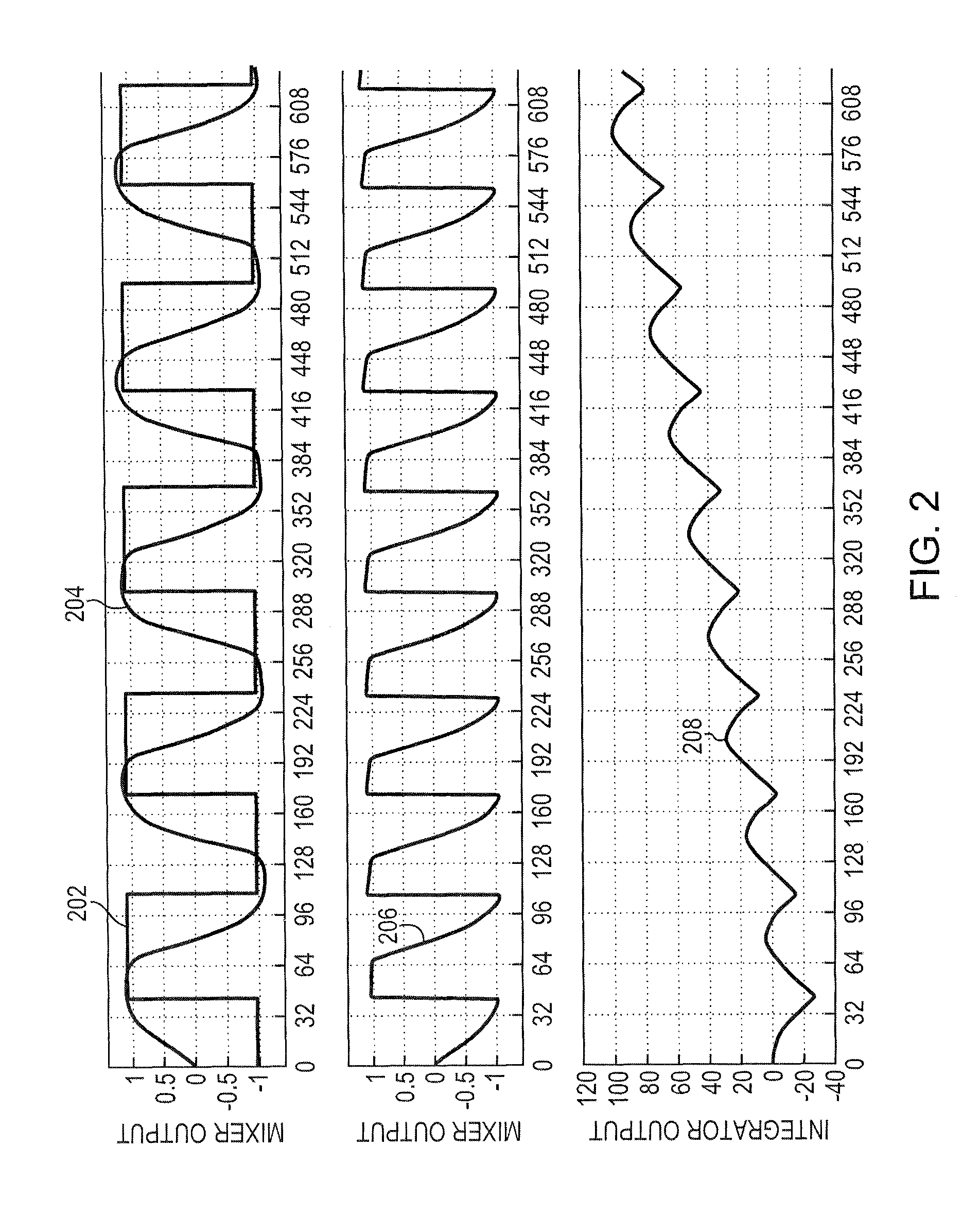
A method and apparatus for measuring latency in a communication path is provided. The technique includes driving a signal such as a square wave on the communication path, such as a write path such that it travels around the write-read path, and sensing a returned signal at one end of the write-read path. A square wave signal corresponding to the square wave driven on the write path is delayed by a predetermined phase thus generating a delayed signal. The returned signal and the delayed signal are mixed, producing a mixed signal. The mixed signal is integrated to obtain an integrated output. The phase by which the delayed signal is shifted is successively adjusted. Returned signals are mixed with such delayed signals until the integrated output is equal to zero. The phase shift amount that results in a nulled integrated output, less a quarter cycle of the square wave, is equal to the round trip latency of the write-read path.
Description
CROSS-REFERENCE TO RELATED APPLICATIONS[0001]The present application is related to the following commonly-owned, copending U.S. patent applications, the content of each of which are incorporated herein by reference:[0002]U.S. Publication No. US2008 / 0080082, published Apr. 3, 2008, by Mehmet Fatih Erden et al., entitled SYNCHRONIZATION FOR DATA COMMUNICATION;[0003]U.S. patent application Ser. No. 12 / 267,330, filed on Nov. 7, 2008, by Barmeshwar Vikramaditya et al., entitled REDUCED READ / WRITE TRANSITION OVERHEAD FOR STORAGE MEDIA;[0004]U.S. patent application Ser. No. 12 / 267,168, filed on Nov. 7, 2008, by Barmeshwar Vikramaditya et al., entitled WRITE CLOCK CONTROL SYSTEM FOR MEDIA PATTERN WRITE SYNCHRONIZATION;[0005]U.S. patent application Ser. No. 12 / 266,677, was filed on Nov. 7, 2008, by Bruce Douglas Buch et al., entitled A WRITE COMPENSATION SYSTEM;[0006]U.S. patent application Ser. No. 12 / 267,215, filed on Nov. 7, 2008, by Bruce Douglas Buch et al. for ELIMINATING SECTOR SYNCHR...
Claims
Application Information
Patent Timeline
Application Date:The date an application was filed.
Publication Date:The date a patent or application was officially published.
First Publication Date:The earliest publication date of a patent with the same application number.
Issue Date:Publication date of the patent grant document.
PCT Entry Date:The Entry date of PCT National Phase.
Estimated Expiry Date:The statutory expiry date of a patent right according to the Patent Law, and it is the longest term of protection that the patent right can achieve without the termination of the patent right due to other reasons(Term extension factor has been taken into account ).
Invalid Date:Actual expiry date is based on effective date or publication date of legal transaction data of invalid patent.

