Shaft seal mounting and method

a technology for sealing mounting and shafts, which is applied in the direction of machine supports, manufacturing tools, other domestic objects, etc., can solve the problems of difficult maintenance and disassembly of seal mountings, complex and costly seal mountings presently in use in such applications, and undesirable gas passage into and out of enclosures, etc., to achieve the effect of easy replacemen

Inactive Publication Date: 2011-02-01
KAUPPILA RICHARD W
View PDF12 Cites 10 Cited by
  • Summary
  • Abstract
  • Description
  • Claims
  • Application Information

AI Technical Summary

Benefits of technology

[0013]The two parts can be disassembled from each other to be removed for seal replacement or repair without the need for removal of the shaft, to simplify maintenance procedures.

Problems solved by technology

In these applications, the passage of gases into and out of the enclosure is typically undesirable, and seals are provided due to the considerable clearance between the hole and shaft.
Seal mountings presently in use in such applications are complex and costly, are difficult to disassemble for maintenance, do not allow lateral shaft adjustments, and do not seal well.

Method used


Image

  • Shaft seal mounting and method
  • Shaft seal mounting and method
  • Shaft seal mounting and method

Examples


Embodiment Construction

[0022]In the following detailed description, certain specific terminology will be employed for the sake of clarity and a particular embodiment described in accordance with the requirements of 35 USC 112, but it is to be understood that the same is not intended to be limiting and should not be so construed inasmuch as the invention is capable of taking many forms and variations within the scope of the appended claims.

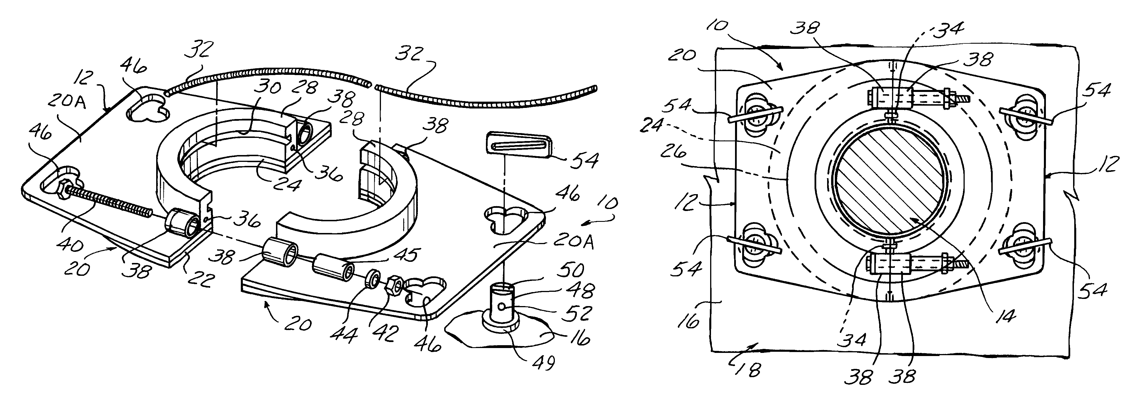
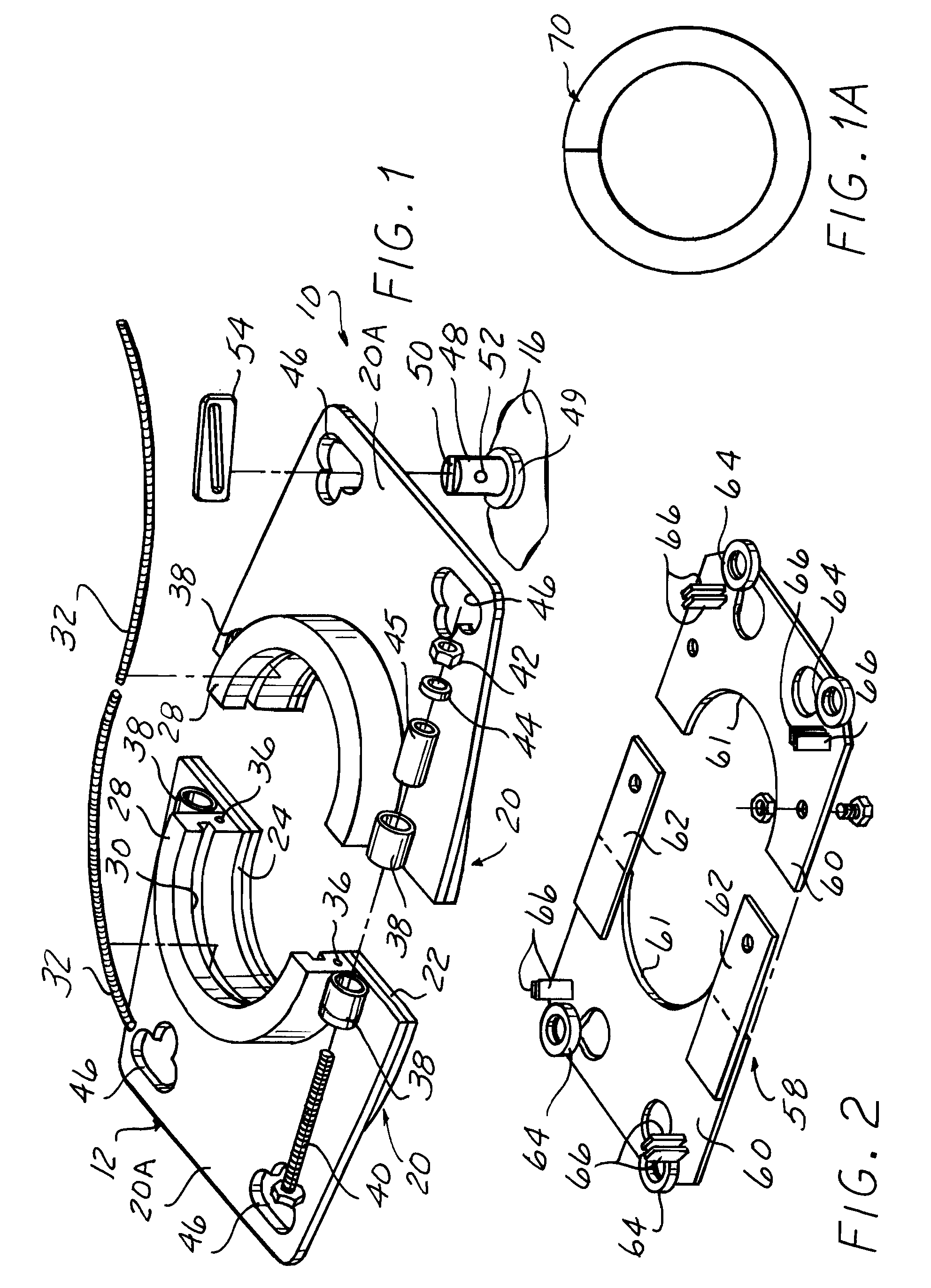
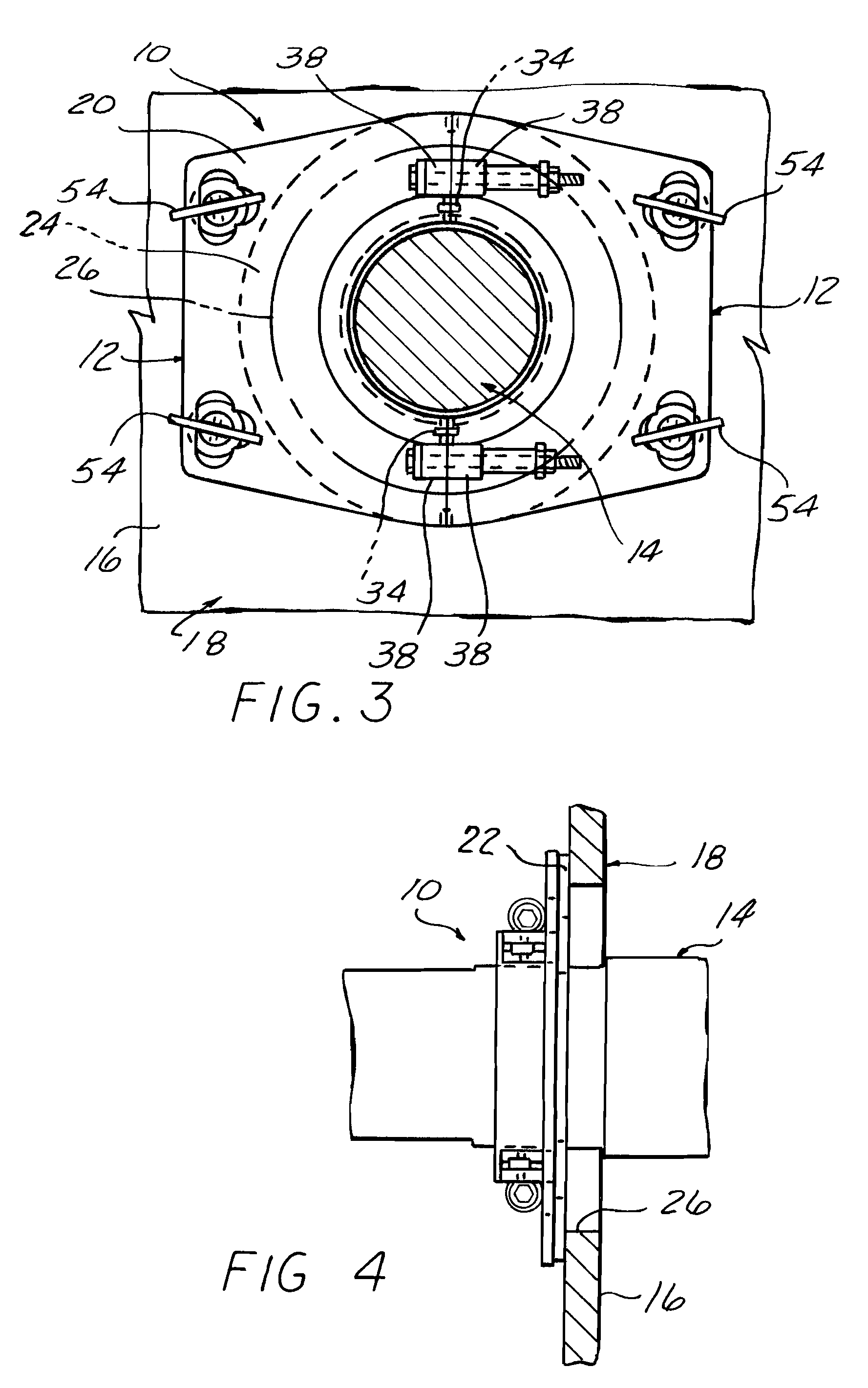
[0023]Referring to the Drawings and particularly FIGS. 1, 3 and 4, the major components of a seal mounting assembly 10 according to the invention is shown.

[0024]This includes two identical mounting parts 12 which are assembled together onto a shaft 14 so as to be centered thereon and drawn against the inside surface of wall 16 of an enclosure 18 when installation is completed.

[0025]The parts 12 may each be comprised of weldments which have segments of a complete bore which is preferably machined with the parts temporarily assembled together for machining.

[0026]A base str...


PUM


Abstract

A shaft seal mounting assembly and method including a pair of semicircular ring segments assembled onto a shaft with a seal held therein engaging the shaft. A flat surface on the base structure holding the ring segments is held against a wall surface extending around a hole through which the shaft passes by a camming arrangement comprised of slotted studs fixed to the wall and received in openings in the base structure. A slotted locking slide bar is received in each stud slot and captured by a cross pin extending through the slot in a respective bar, the side bar slot sloping so as to cam the base structure towards the wall surface when the locking slide bar is driven through the stud slot.

Description

CROSS REFERENCE TO RELATED APPLICATIONS[0001]This application claims the benefit of U.S. provisional application No. 60 / 719,739 filed on Sep. 22, 2005.BACKGROUND OF THE INVENTION[0002]This invention concerns shaft sealing mountings and more particularly mountings for such shaft seals used in industrial applications such as in steel making apparatus in which a shaft passes through a hole in a wall of an enclosure with a considerate clearance therebetween. In these applications, the passage of gases into and out of the enclosure is typically undesirable, and seals are provided due to the considerable clearance between the hole and shaft. This clearance is required since the hole must be large enough to accommodate lateral shaft movements resulting from bearing wear adjustments, temperature shift induced expansion and contraction, etc.[0003]Seal mountings presently in use in such applications are complex and costly, are difficult to disassemble for maintenance, do not allow lateral sha...

Claims


Application Information

Patent Timeline
Patent Type & Authority Patents(United States)
IPC IPC(8): F16L3/00
CPCF16J15/3268Y10T16/05
Inventor KAUPPILA, RICHARD W.
Owner KAUPPILA RICHARD W
Why Eureka
Try Eureka