Vehicular room illuminating lamp

a technology for illuminating lamps and vehicles, which is applied in the direction of lighting and heating equipment, transportation and packaging, and support devices, etc. it can solve the problems of poor comfort and disgusting feeling of the occupant, and achieve the effect of preventing the wasteful consumption of batteries, reducing the disgusting feeling of the occupant, and reducing the consumption of energy

Inactive Publication Date: 2011-02-01
YAZAKI CORP
View PDF5 Cites 5 Cited by
  • Summary
  • Abstract
  • Description
  • Claims
  • Application Information

AI Technical Summary

Benefits of technology

[0016]In this connection, the present invention has been made in order to solve the above-described problem, and it is an object of the present invention to provide a vehicular room illuminating lamp capable of preventing an increase of the wasteful consumption of the battery and the disgusting feeling of the occupant.
[0020]According to the present invention, when the door mode is selected by the first switch, the voltage is applied only to the wire for the individual mode connected to the illumination unit corresponding to the door indicated to be open by the door open / close signal. Therefore, only the light source of the illumination unit corresponding to the opened door is turned on. Accordingly, it is possible to prevent the wasteful consumption of the battery, the increase of the disgusting feeling of the occupant, or the deterioration of the comfortableness.

Problems solved by technology

Moreover, the unnecessary light-on of the lamp L1 or L2 causes an occupant (passenger on the seat that does not correspond to the opened door) to have a disgusting feeling, and comfortableness is impaired.

Method used


Image

  • Vehicular room illuminating lamp
  • Vehicular room illuminating lamp
  • Vehicular room illuminating lamp

Examples


Embodiment Construction

[0038]A description will be made below of embodiments of the present invention based on the drawings.

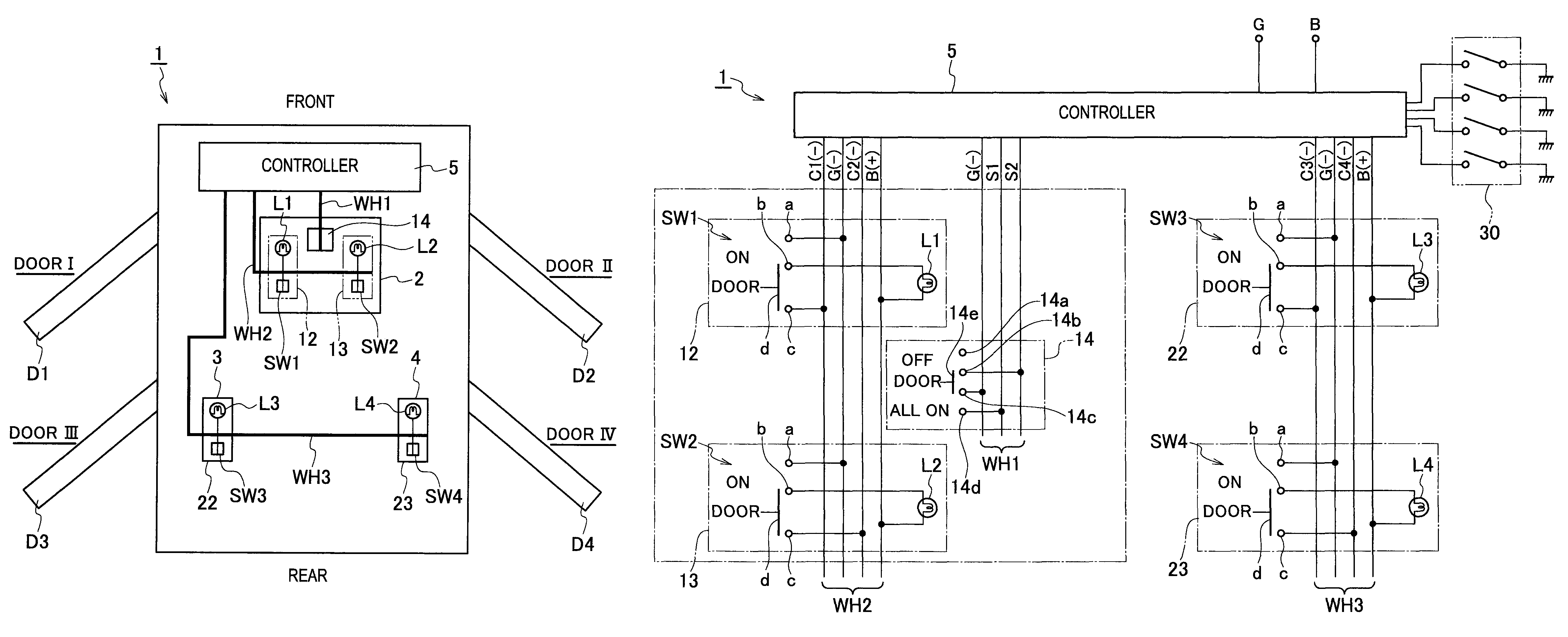
[0039]As shown in FIG. 3, a vehicular room illuminating lamp 1 includes: a single illuminating device 2 for a map lamp, which is provided on a ceiling on a front seat side of a vehicle cabin; two illuminating devices 3 and 4 for personal lamps, which are provided on a ceiling on a rear seat side of the vehicle cabin; a controller 5 that controls these illuminating devices 2, 3 and 4; a wire harness WH1 for a switching switch and a wire harness WH2 for the map lamp, which are cabled between the illuminating device 2 for a map lamp and the controller 5; and a wire harness WH3 for the personal lamps, which is cabled between the illuminating devices 3 and 4 for the personal lamps and the controller 5.

[0040]As shown in FIG. 5 to FIG. 8, the single illuminating device 2 for the map lamp includes: a housing 10 fixed to the ceiling; a cover member 11 that covers a vehicle cabin side of the h...


PUM


Abstract

A vehicular room illuminating lamp includes: a plurality of illumination units applying voltages through courtesy wires thereof to lamps which irradiate positions in a vehicle cabin, the positions corresponding to four doors; a mode switch capable of selecting an all-lights-on mode, a door mode and a light-off mode; and a controller that individually receives a mode selection signal of the mode switch and respective door open / close signals of the four doors. The controller applies the voltages to all of the courtesy wires in the all-lights-on mode, applies the voltage only to the courtesy wire of the illumination unit corresponding to the door indicated to be open by the door open / close signal in the door mode, and does not apply the voltage to any of the courtesy wires irrespective of states of the door open / close signals in the light-off mode.

Description

CROSS REFERENCE TO RELATED APPLICATION[0001]This application is based upon and claims the benefit of priority from Japanese Patent Application No. 2007-236642 filed on Sep. 12, 2007, the entire contents of which are incorporated herein by reference.BACKGROUND OF THE INVENTION[0002]1. Field of the Invention[0003]The present invention relates to a vehicular room illuminating lamp capable of switching a mode between a mode in which a light source can be turned on / off irrespective of an open / close state of a door and a mode in which the light source can be turned on / off in response to the open / close state of the door.[0004]2. Description of the Related Art[0005]A conventional vehicular room illuminating lamp is disclosed in Japanese Patent Laid-Open Publication No. 2006-62640. As shown in FIG. 1, this vehicular room illuminating lamp 100 includes: a housing 102; a cover member 103; two illumination units 104 and 105; a mode switch 106; and a wire harness WH in a flat shape. The housing ...

Claims


Application Information

Patent Timeline
Patent Type & Authority Patents(United States)
IPC IPC(8): B60Q7/00B60Q1/14
CPCB60Q3/0279B60Q3/0293B60Q3/74B60Q3/80
Inventor NAGAI, KENTARONAKAYAMA, YUSUKE
Owner YAZAKI CORP
Why Eureka
Try Eureka