
Computer system and control method

a computer system and control method technology, applied in the field of computer systems, can solve the problems of more expensive ssds than hdds, and achieve the effects of reducing the waste of high-speed storage media, reducing the cost of ssds, and improving the performance of data with a high write access

Active Publication Date: 2017-07-11
HITACHI LTD
View PDF9 Cites 0 Cited by
  • Summary
  • Abstract
  • Description
  • Claims
  • Application Information

AI Technical Summary

Benefits of technology

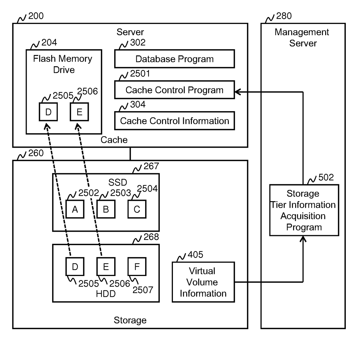
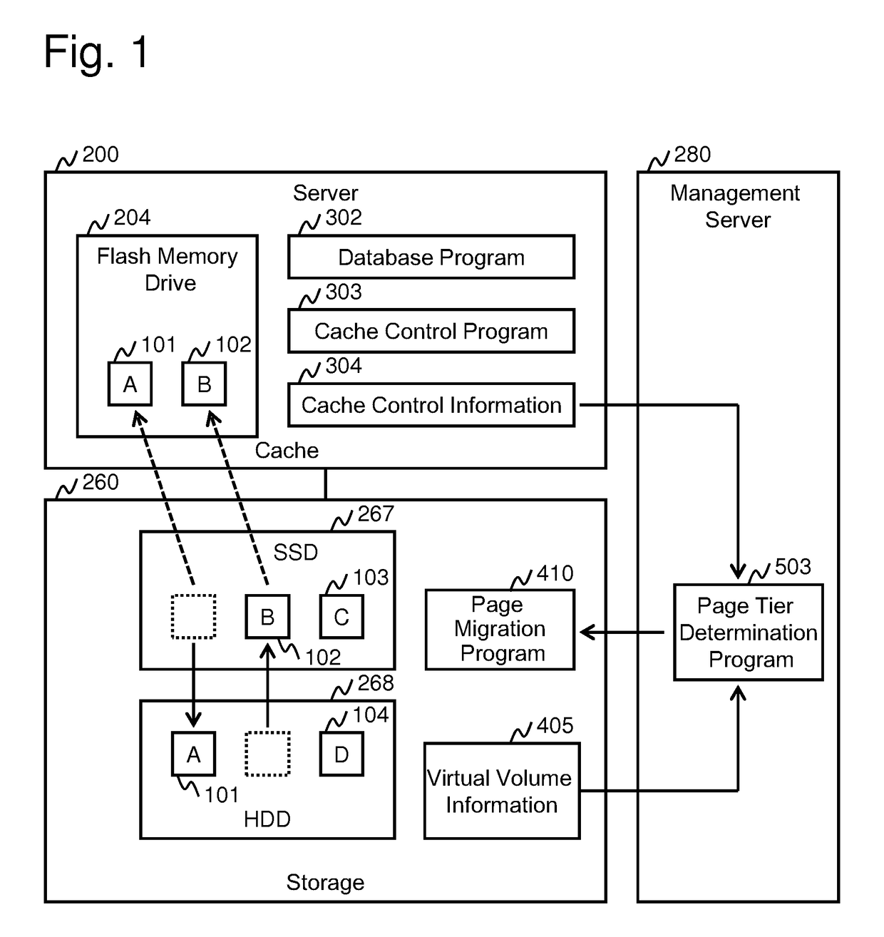
[0009]According to the prior art system, data having a high I / O frequency tends to be placed onto the high-level storage tier of the storage system and also cached in the server cache, therefore, the same data will be stored in a duplicated manner to both the server cache and the upper-level storage tier of the storage system, and high-speed storage media will be consumed wastefully. According to the computer system of the present invention, control is performed so as to prevent data stored in the server cache from being placed onto the high-level storage tier of the storage system, or to prevent data placed onto the upper-level storage tier of the storage system from being cached in the server cache, so that larger amount of data can be placed onto the high-speed storage media such as the server cache or the upper-level storage tier of the storage system, and the I / O performance of the computer system can thereby be improved. According to the computer system of the present invention, the data cached in the server cache and having a high write rate is placed onto the high-speed storage tier of the storage system, so that the I / O performance of the data having a high write access can also be improved.

Problems solved by technology

In general, SSDs are more expensive than HDDs, so that if it is necessary to construct and operate computer systems within a limited budget, the storage areas of the SSDs must be utilized efficiently, since it is not possible to allocate a large SSD capacity.

Method used


Image

  • Computer system and control method
  • Computer system and control method
  • Computer system and control method

Examples


embodiment 1

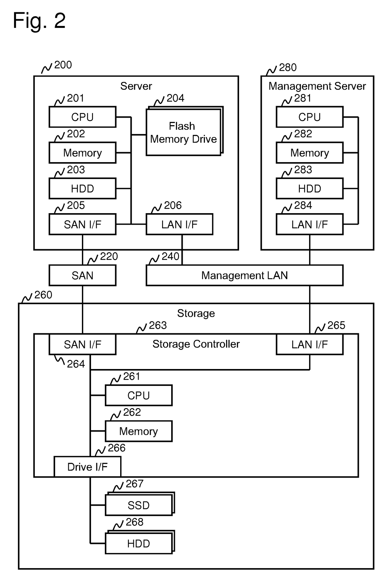
[0038]FIG. 2 illustrates a configuration of the computer system according to embodiment 1. The server 200 reads data from the storage system 260 via a SAN (Storage Area Network) 220, and writes data into the storage system 260 (sometimes abbreviate as “storage 260”). The management server 280 is connected to the server 200 and the storage system 260 via a management LAN 240 to gather information from the server 200 and the storage system 260 and to transmit instructions to the server 200 and the storage system 260.

[0039]The server 200 is composed of a CPU 201, a memory 202, an HDD 203, a flash memory drive 204, a SAN I / F 205 and a LAN I / F 206. The CPU 201 is for executing various programs used in the server 200 such as a database program described later, wherein when the server 200 is started or the like, the CPU loads the programs and data stored in the HDD 203 to the memory 202 and executes the programs to realize predetermined functions. In the present specification, there are de...

modified example 1

[0077]According to embodiment 1 described above, the storage tiers are controlled (changed) in units of pages managed by the storage system 260, but for example, the storage tiers can also be controlled in units of objects or portions of the objects managed by the application program, such as the database program 302, which can be a database table or an index. The present embodiment describes the information managed by the computer system according to such example. FIG. 15 shows the object location information 305 created by the database program 302. The area specified by an object name 701, a start address 703 and a length 704 of each row shows the area of an object used in the database program 302. Incidentally, the objects specified by the object name 701 are all objects managed by the database program 302 by storing them in the volume(s) of the storage system 260. An object type 702 shows the type of the objects. The area of the object shows that the object is placed onto an are...

modified example 2

[0082]According to the computer system of embodiment 1, the server cache status acquisition program 501, the storage tier information acquisition program 502 and the page tier determination program 503 are prepared in the management server 280, but it is also possible to provide them for the storage system 260 and to have the storage system 260 acquire the cache control information 304 directly from the server 200 to determine whether page migration is necessary or not. In that case, the process of FIG. 11 can be set to be executed each time when an update of the cache control information 304 occurs (such as when the server 200 accesses the virtual volume and the state of the data stored in the flash memory drive 204 which is a server-side cache is changed).

[0083]Another possible example can have the server cache status acquisition program 501, the storage tier information acquisition program 502 and the page tier determination program 503 provided for the server 200, and have the s...


PUM


Abstract

A computer system according to the present invention is composed of a server 200 having a flash memory drive 204 for cache, a storage system 260 having storage tiers composed of an SSD 267 and an HDD 268, and a management server having a page tier determination program 503 for determining the storage tier to which data is to be stored. The page tier determination program 503 migrates data having a high read access rate out of the pages having a high cache rate to the flash memory drive 204 to a storage tier of the HDD 268, and confirms so that data is not stored in a duplicated manner to the flash memory drive 204 and the SSD 267. Further, the data having a relatively high write access rate is migrated to the storage tier of the SSD 267 so as to prevent deterioration of write process performance.

Description

TECHNICAL FIELD[0001]The present invention relates to a computer system, and specifically, relates to an art of managing storage areas in a computer system having a storage system with storage tiers composed of different types of storage media, and a server having a cache.BACKGROUND ART[0002]Recently, the use of SSDs (Solid State Drives) which are storage media having higher performance than HDDs (Hard Disk Drives) is spreading. In general, SSDs are more expensive than HDDs, so that if it is necessary to construct and operate computer systems within a limited budget, the storage areas of the SSDs must be utilized efficiently, since it is not possible to allocate a large SSD capacity. One prior art technique for efficiently utilizing a small capacity of high-performance storage media is a hierarchical storage management (tiered storage management) technique that provides to a storage system a storage tier composed of an expensive and high-performance storage media and a low-performan...

Claims


Application Information

Patent Timeline
Patent Type & Authority Patents(United States)
IPC IPC(8): G06F12/08G06F12/0866G06F3/06G06F12/0888
CPCG06F12/0888G06F3/061G06F3/0604G06F3/067G06F3/0631G06F3/0649G06F3/0685G06F12/0866G06F2212/604
Inventor HAYASHI, SHINICHIFUNAYA, YUSUKE
Owner HITACHI LTD
Learn More