Control of system coolant to facilitate two-phase heat transfer in a multi-evaporator cooling system

a cooling system and control system technology, applied in the field of heat transfer mechanisms, can solve the problems of increasing power consumption, increasing heat load and heat flux, and increasing device performance challenges, so as to reduce power consumption, increase the amount of heat and heat density (i.e., heat per unit volume) and increase computer performance.

Active Publication Date: 2011-03-10
LENOVO GLOBAL TECH INT LTD
View PDF52 Cites 72 Cited by
  • Summary
  • Abstract
  • Description
  • Claims
  • Application Information

AI Technical Summary

Benefits of technology

[0006]As the need for increased computer performance continues to increase, the amount of heat and heat density (i.e., heat per unit volume) continues to increase. This, plus the desire to reduce power consumption in the typical data center, drives a need for an effective two-phase liquid-cooling solution. In a two-phase liquid-cooling solution, the heat that is transferred by convection is done so principally by a change in coolant phase. Building on this approach, a two-phase liquid-cooling solution is presented herein for effectively cooling a plurality of electronic devices in parallel.
[0007]Briefly summarized, the present invention comprises in one aspect a cooling system which comprises a plurality of evaporators configured to couple to a plurality of electronic devices to be cooled, a coolant loop for passing system coolant through the plurality of evaporators, and a control unit for maintaining pressure of system coolant within the coolant loop. The coolant loop includes a plurality of coolant branches coupled in parallel, with each coolant branch being coupled in fluid communication with a respective evaporator of the plurality of evaporators. The control unit maintains pressure of system coolant at a system coolant supply side of the plurality of coolant branches coupled in parallel within a specific pressure range at or above saturation pressure of the system coolant for a desired saturation temperature of system coolant into the plurality of evaporators, to thereby facilitate two-phase heat transfer in the plurality of evaporators from the plurality of electronic devices to the system coolant at the desired saturation temperature.
[0008]In another aspect, a cooled electronics system is provided which includes a plurality of electronic devices capable of generating differing amounts of heat dependent on the operational states thereof, and a cooling system for cooling the plurality of electronic devices. The cooling system includes a plurality of evaporators coupled to

Problems solved by technology

Despite these advantages, providing many electronic devices in a small footprint can create device performance challenges.
One of these challenges is thermal management of the overall environment.
Heat dissipation issues, if unresolved, can result in electronic and mechanical failures that will affect system performance, irrespective of the size of the environment.
In many computing environments, microprocessors continue to increase in performance, with the active circuitry of the microprocessor chip being driven to an ever smaller footprint, leading

Method used


Image

  • Control of system coolant to facilitate two-phase heat transfer in a multi-evaporator cooling system
  • Control of system coolant to facilitate two-phase heat transfer in a multi-evaporator cooling system
  • Control of system coolant to facilitate two-phase heat transfer in a multi-evaporator cooling system

Examples


Embodiment Construction

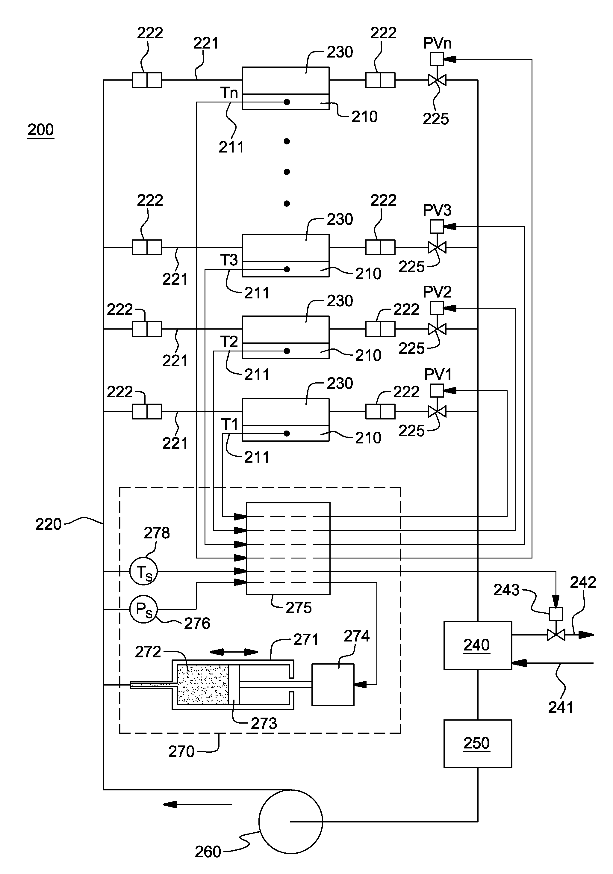
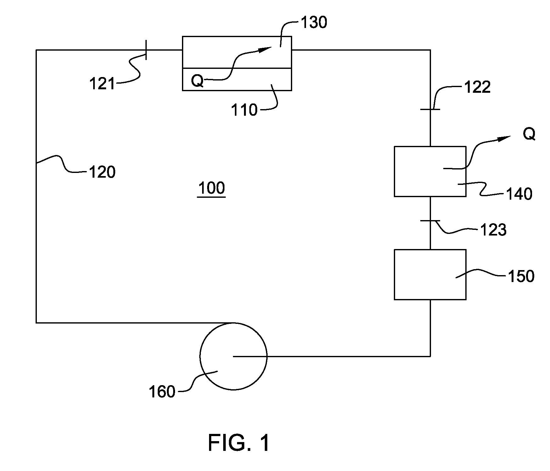
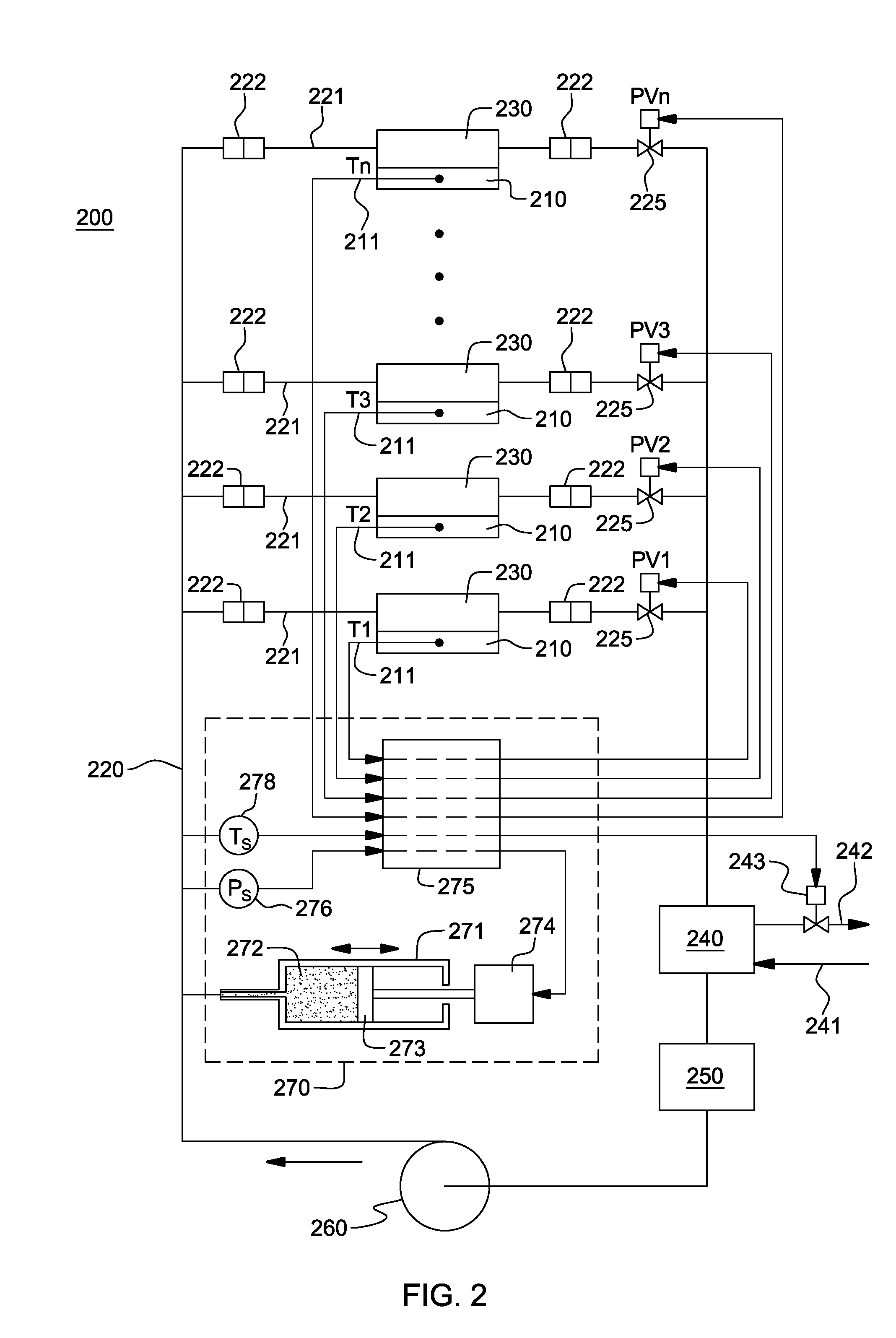
[0019]As used herein, “electronic device” comprises one or more heat-generating electronic devices of a computer system or other electronic system requiring cooling. In one example, the electronic device is or includes an integrated circuit chip, a semiconductor chip and / or any other electronic device(s) requiring cooling, and may either be unpackaged or packaged in an electronic module. As one example, the electronic device may comprise part of an electronic system disposed, for example, in an electronics rack, such as a rack-mounted server system. A “liquid-to-air heat exchanger” means any heat exchange mechanism through which liquid coolant can circulate; and includes, one or more discrete heat exchange devices coupled either in series or in parallel. A heat exchange device may comprise, for example, one or more coolant flow paths, formed of thermally conductive fluid conduits (such as copper, brass or other tubing) in thermal contact with a plurality of air-cooled fins (formed o...


PUM


Abstract

A cooling system and method are provided for facilitating two-phase heat transfer from an electronics system including a plurality of electronic devices to be cooled. The cooling system includes a plurality of evaporators coupled to the electronic devices, and a coolant loop for passing system coolant through the evaporators. The coolant loop includes a plurality of coolant branches coupled in parallel, with each coolant branch being coupled in fluid communication with a respective evaporator. The cooling system further includes a control unit for maintaining pressure of system coolant at a system coolant supply side of the coolant branches within a specific pressure range at or above saturation pressure of the system coolant for a given desired saturation temperature of system coolant into the evaporators to facilitate two-phase heat transfer in the plurality of evaporators from the electronic devices to the system coolant at the given desired saturation temperature.

Description

BACKGROUND[0001]The present invention relates in general to heat transfer mechanisms, and more particularly, to cooling apparatuses and methods for removing heat generated by a plurality of electronic devices. Still more particularly, the present invention relates to fluidic cooling apparatuses and methods for cooling a plurality of electronic devices.[0002]The industry trend has been to continuously increase the number of electronic devices within a computing system environment. Compactness allows for selective fabrication of smaller and lighter devices that are more attractive to the consumer. Compactness also allows circuits to operate at higher frequencies and at higher speeds due to the shorter electrical connection distances in such devices. Despite these advantages, providing many electronic devices in a small footprint can create device performance challenges. One of these challenges is thermal management of the overall environment. Heat dissipation issues, if unresolved, ca...

Claims


Application Information

Patent Timeline
IPC IPC(8): F25B49/02F25B7/00F25D17/02F25D31/00F28D15/00F25B41/04
CPCF28D15/0266H05K7/20381F28D15/06
Inventor CAMPBELL, LEVI A.CHU, RICHARD C.ELLSWORTH, JR., MICHAEL J.IYENGAR, MADHUSUDAN K.SIMONS, ROBERT E.
Owner LENOVO GLOBAL TECH INT LTD
Why Eureka
Try Eureka