Centralized monitoring apparatus

a monitoring apparatus and central monitoring technology, applied in the direction of program control, refrigeration components, heat storage plants, etc., can solve the problems of unsolved above power consumption problem and wasteful consumption of electric power by the temperature variable devi

Active Publication Date: 2014-07-01
PHC HLDG CORP
View PDF26 Cites 0 Cited by
  • Summary
  • Abstract
  • Description
  • Claims
  • Application Information

AI Technical Summary

Benefits of technology

[0008]Since disturbance such as opening and closing of the door of the storage have different frequency distributions in a day, for example, depending on a usage pattern of the preservation equipment, it is desirable for the electric power saving of the temperature variable device that the set temperature within the storage is increased and decreased within a range not affecting the preservation of the preservation object, for example. However, since the set temperature is fixed in the above preservation equipment on the basis of certain disturbance, it is problematic that electric power is wastefully consumed by the temperature variable device operating at the fixed set temperature at the timing when the effect of disturbance is not so great, for example.

Problems solved by technology

However, since the set temperature is fixed in the above preservation equipment on the basis of certain disturbance, it is problematic that electric power is wastefully consumed by the temperature variable device operating at the fixed set temperature at the timing when the effect of disturbance is not so great, for example.
Therefore, the above power consumption problem remains unsolved.

Method used


Image

  • Centralized monitoring apparatus
  • Centralized monitoring apparatus
  • Centralized monitoring apparatus

Examples


Embodiment Construction

[0021]At least the following details will become apparent from descriptions of this specification and of the accompanying drawings.

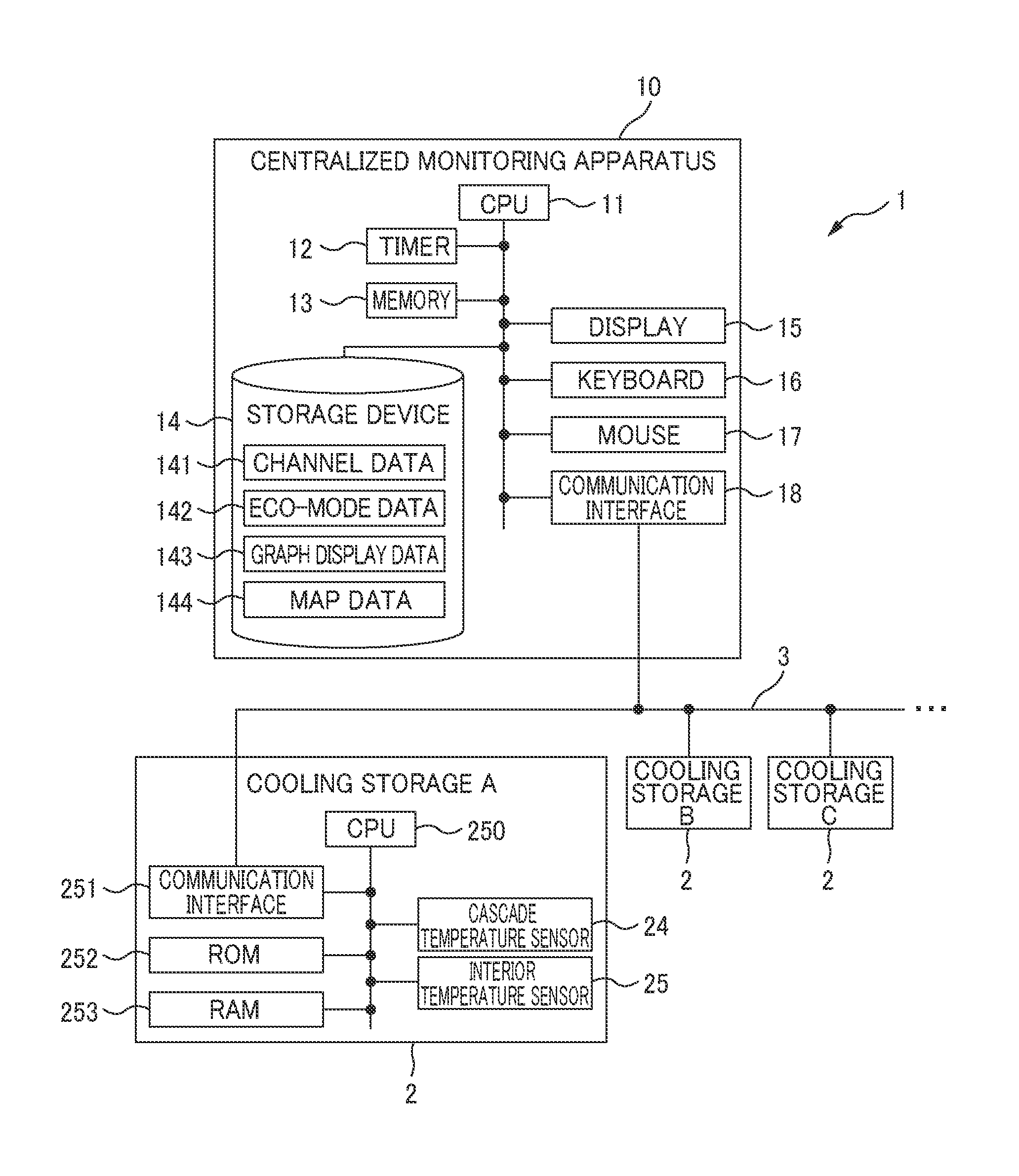
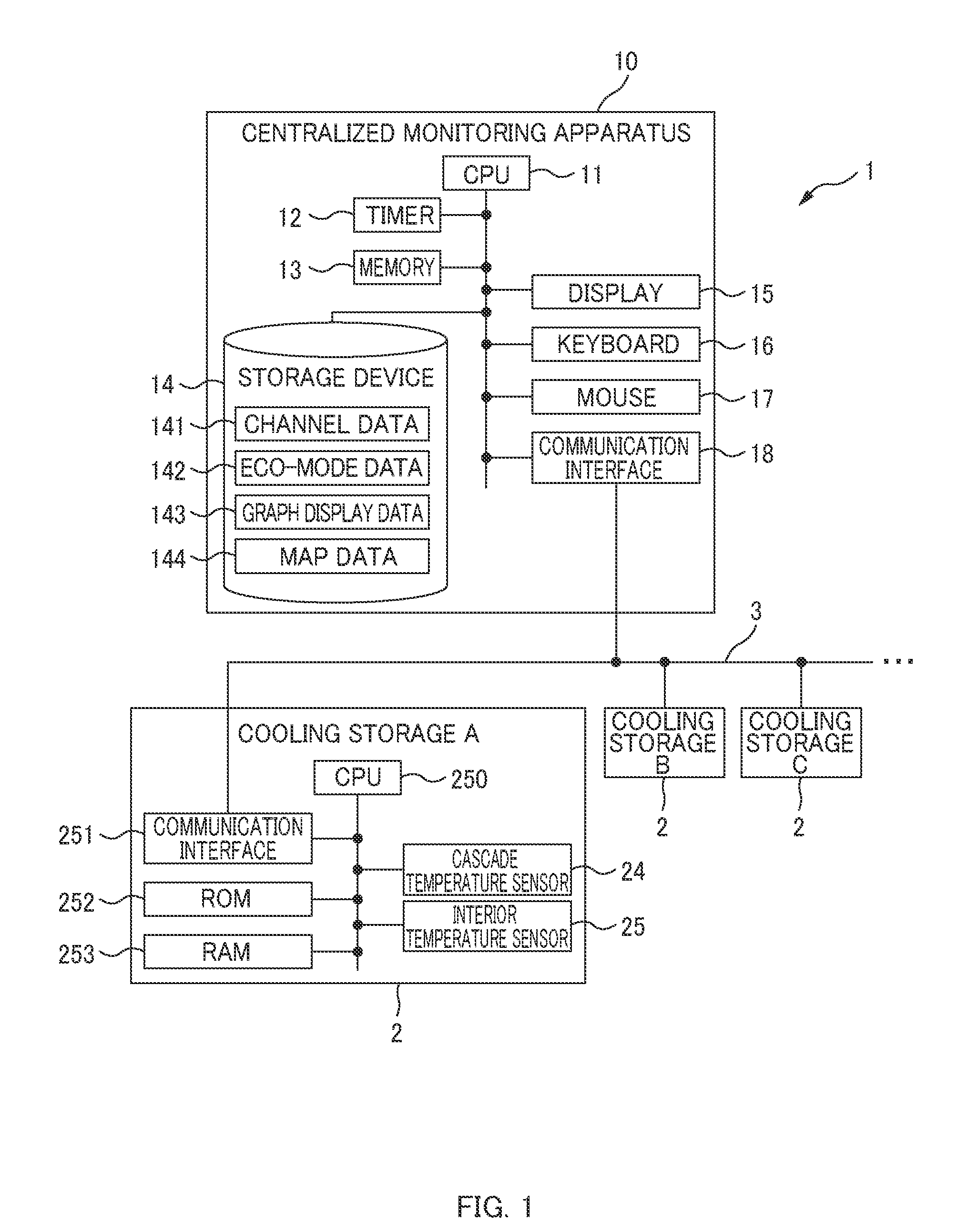
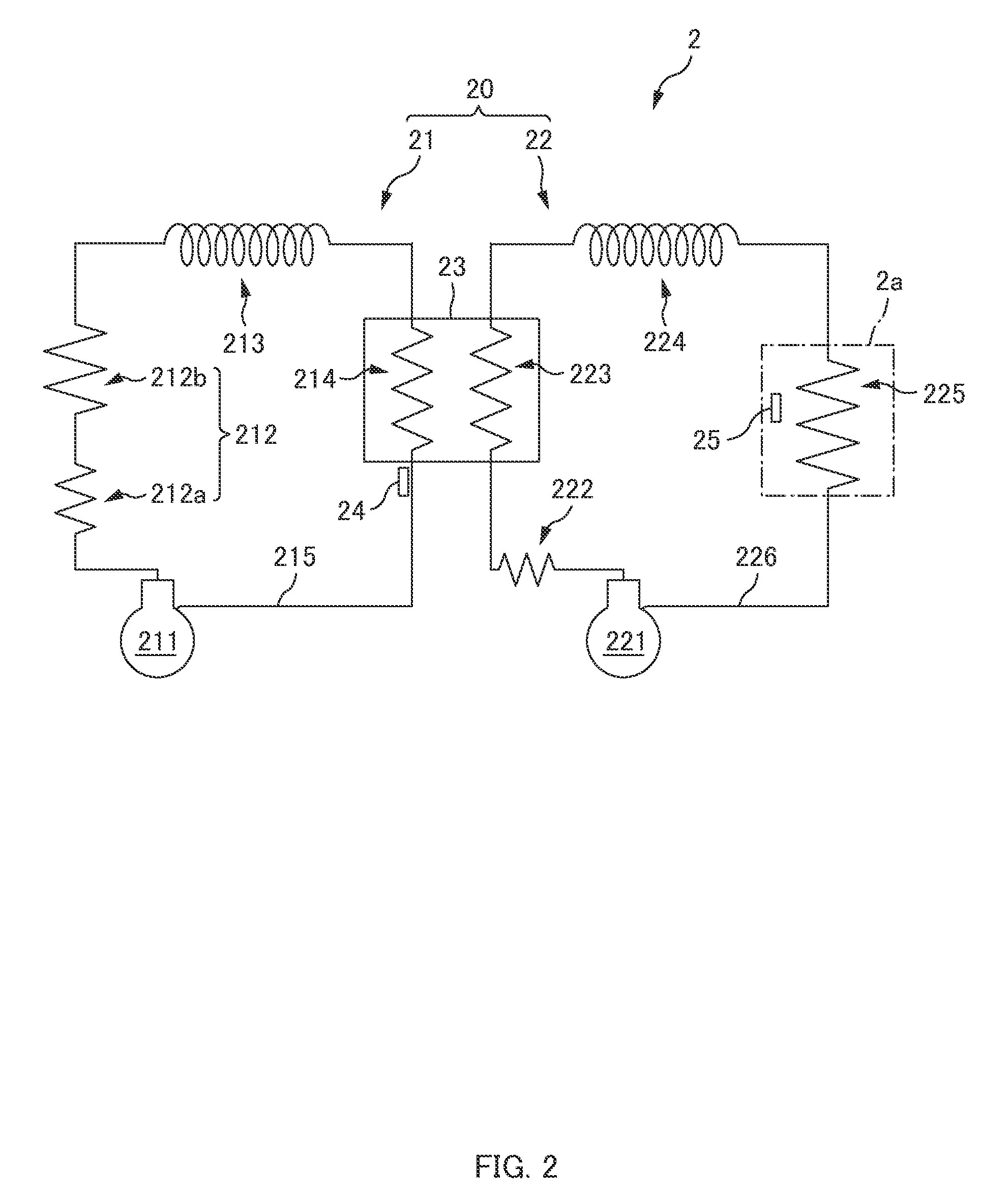
[0022]A centralized monitoring apparatus 10 of an embodiment will be described with reference to FIGS. 1 to 8. FIG. 1 is a block diagram of an example of the centralized monitoring system 1 of the embodiment. FIG. 2 is a circuit diagram of an example of a refrigerating circuit 20 of the embodiment. FIG. 3 is a chart of an exemplary configuration of eco-mode data 142 of the embodiment. FIG. 4 is a chart of an exemplary configuration of graph display data 143 of the embodiment. FIG. 5 is a chart of an exemplary configuration of map data 144 of the embodiment. FIG. 6 is a schematic of an example of eco-mode setting screen 1420 of the embodiment. FIG. 7 is a schematic of an example of a graph display area 1430 of a display screen 1400 of the embodiment. FIG. 8 is a schematic of an example of a map display area 1440 of the display screen 1400 of the embodimen...


PUM

PropertyMeasurementUnit
unit timeaaaaaaaaaa
timeaaaaaaaaaa
temperatureaaaaaaaaaa

Abstract

A centralized-monitoring apparatus, which centralized monitors a device including a storage, a temperature sensor to detect a temperature therein, and a temperature-variable device to cool or heat inside the storage such that the temperature reaches a set object-preservation temperature, comprises: an input device to be input with first information indicative of a time zone in which the temperature-variable device performing power-saving operation and second information indicative of a set temperature of the time zone; a storage device to store the first-and-second information from the input device; a timing device to measure a current time; and a control device to control the temperature-variable device, based on the first-and-second information and current time, so as to start operation of turning the temperature to the set temperature when the current time reaches a starting time of the time zone, and terminate the operation when the current time reaches an ending time thereof.

Description

CROSS-REFERENCE TO RELATED APPLICATION[0001]This application claims the benefit of priority to Japanese Patent Application No. 2009-036937, filed Feb. 19, 2009, of which full contents are incorporated herein by reference.BACKGROUND OF THE INVENTION[0002]1. Field of the Invention[0003]The present invention relates to a centralized monitoring apparatus.[0004]2. Description of the Related Art[0005]Preservation equipment is known that includes a temperature variable device that cools or heats the inside of a storage such that the temperature within the storage reaches a set temperature for preserving a preservation object. To detect failure, etc., of the temperature variable device of the preservation equipment, a centralized monitoring apparatus is disclosed that monitors the temperature within the storage detected by a temperature sensor to determine presence of failure, etc., by comparing the detected temperature with a set temperature (e.g., Japanese Patent Application Laid-Open Pub...

Claims


Application Information

Patent Timeline
Patent Type & Authority Patents(United States)
IPC IPC(8): F24F11/04F25B29/00F25D23/12F28F13/00F28F27/00G01K3/00G05D23/00G05D23/19
CPCF25D29/00F25B27/00F25B2700/21175F25D2400/361F25D2600/02F25D2700/12F25D2700/14G01K2207/04
Inventor SONODA, YASUAKITANAKA, MASANAGANONO, IKUENAKAMURA, SHIGEYUKI
Owner PHC HLDG CORP
Why Eureka
Try Eureka