Apparatus and process for stacking pieces of material

a technology of apparatus and material, applied in the direction of stacking articles, soldering apparatus, auxillary welding devices, etc., can solve the problems of unassisted manual processes, one or more sub-millimeter dimensions of pieces of material, and inconvenient stacking, etc., to achieve precise and accurate control of piece placement, efficient and effective stacking, and accurate alignment

Inactive Publication Date: 2011-02-15
NAT RES COUNCIL OF CANADA
View PDF13 Cites 4 Cited by
  • Summary
  • Abstract
  • Description
  • Claims
  • Application Information

AI Technical Summary

Benefits of technology

[0008]The one or more platens may be transversely movable or fixed in respect of transverse movement. Preferably, the one or more platens are fixed in respect of transverse movement. Preferably, there is one platen along the length of the assembly region. When pieces of material are placed in the assembly region, the press rams and the one or more platens can be used to immobilize or partially immobilize the pieces in the assembly gap permitting accurate and precise alignment of the pieces relative to each other in the assembly region. The press rams and the one or more platens may be longitudinally movable along the length of the assembly region. The press rams and the one or more platens are preferably fixed in respect of such longitudinal movement. Having a plurality of movable press rams instead of one press ram provides smaller immobilization areas along the length of the pieces thereby providing better control over alignment of the pieces and providing the ability to accommodate stacking of smaller pieces.
[0013]The press rams are then tightened so that the pieces cannot move in the assembly region. Preferably, the press rams are tightened one at a time, and preferably in linear order, providing the opportunity to push the edge of the pieces down into the assembly region so that they are touching a bottom of the assembly region before each press ram is tightened along the length of the assembly region. This permits more accurate face to face alignment of the pieces, helping to overcome a tendency for the pieces to warp along their length. Further, once all of the press rams are tightened, one or more press rams can be loosened and re-tightened, if necessary, to permit pushing of the pieces further down into the assembly region and / or to adjust alignment or position of the pieces. One or more connectors are applied to the edge, preferably at predetermined and indicated places, to hold the pieces together. The press rams are then loosened and a third piece is placed in the assembly region, aligned as desired with the first and second pieces in the stack, and the process of tightening the press rams and connecting the pieces repeated. As many pieces as desired may be added to the stack in a similar manner. For variation in stack profile, it is possible to flip the stack around in the assembly region before placement of additional pieces.
[0015]The apparatus of the present invention is useful for stacking a plurality of pieces of material. Two or more pieces, preferably four or more pieces, may be stacked efficiently and effectively. The apparatus is particularly useful for stacking pieces having sub-millimeter thicknesses. Sub-millimeter thick pieces are difficult to handle and tend to warp along their length making it difficult to form a stable, accurately aligned stack of pieces. The present apparatus permits immobilization of individual pieces during stack construction in a controlled and precise fashion thereby permitting precise alignment of subsequent pieces in relation to preceding pieces as the stack is constructed in the apparatus. Precise and accurate control of piece placement in the assembly region also permits stacking the pieces in a staggered or off-set manner providing excellent control over stack profile. Alignment may be automated using a camera-based closed-loop control system.

Problems solved by technology

Further, unassisted manual processes are imprecise in terms of placement and off-set adjustment resulting in end products that may not be within specified tolerances.
In particular, pieces of material having one or more sub-millimeter dimensions, light-weight material and / or very flexible material (e.g. plastic strips) are difficult to handle.
Further, as material properties change (e.g. density, volume) there is a greater tendency, particularly for longer pieces of material, to warp or buckle thereby increasing the difficulty of constructing accurately and precisely positioned stacked piles of the material.
At sub-millimeter thicknesses (e.g. a few tens of microns), pieces of material are especially difficult to handle for stack fabrication applications.

Method used


Image

  • Apparatus and process for stacking pieces of material
  • Apparatus and process for stacking pieces of material
  • Apparatus and process for stacking pieces of material

Examples


Embodiment Construction

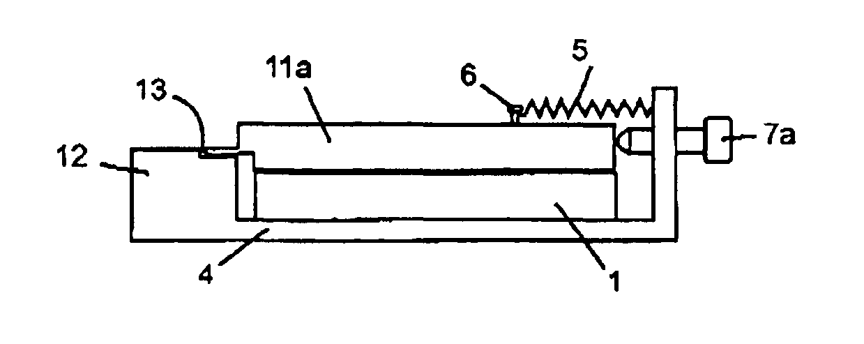
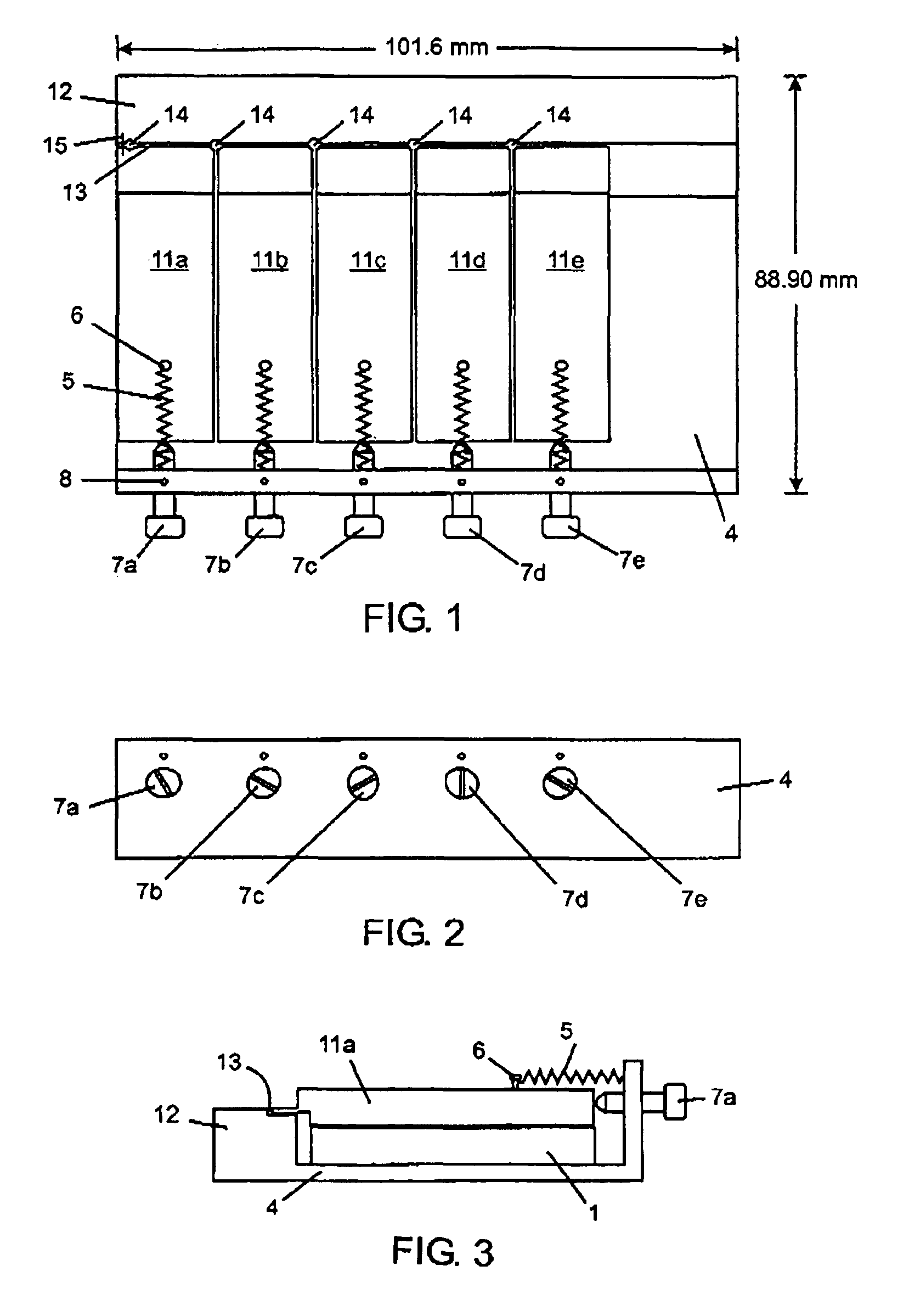
[0030]An embodiment of an apparatus of the present invention for assembling a stack of ribbons is depicted in FIGS. 1-3. In FIGS. 1-3, all dimensions are in millimeters (mm) unless otherwise stated. Referring to FIGS. 1-3, the fixture comprises five linear ball slide assemblies 1 (only one labeled) (available from Del-Tron Precision Inc. of Bethel Conn.) on which five movable press rams 11a-e are bolted. The ball slide assemblies are bolted to base plate 4. Fixed platen 12 is an integral part of the base plate. Five torsion wire springs 5 (only one labeled) connect each of the movable rams to the base plate. The springs are bolted to the movable rams with socket head cap screws 6 (only one labeled) and to the base plate with set screws 8 (only one labeled). Five fine pitch adjustment screws 7a-e are mounted in the base plate through threaded apertures so that the tip of each fine pitch screw contacts the movable rams. The base plate, including the fixed platen, and the movable rams ...


PUM

PropertyMeasurementUnit
off-set distanceaaaaaaaaaa
sizeaaaaaaaaaa
dimensionsaaaaaaaaaa

Abstract

An apparatus for stacking a plurality of pieces of material has an assembly region, one or more platens on a first longitudinal side of the assembly region, and, a plurality of press rams on a second longitudinal side of the assembly region opposite the first longitudinal side. The press rams are movable transversely across the assembly region to immobilize or partially immobilize pieces of material in the assembly region permitting accurate and precise alignment of the pieces relative to each other in the assembly region.

Description

FIELD OF THE INVENTION[0001]The present invention relates to an apparatus and process to facilitate stacking of pieces of material, particularly pieces of material having one or more dimensions in the sub-millimeter range.BACKGROUND OF THE INVENTION[0002]Stacking pieces of material in an accurate and precise fashion to form stacks having various profiles can be done manually by hand and unassisted when they are large and easy to handle. However, for micro manufacturing applications, when the piece of material is smaller, specialized micromanipulation tools are necessary to assist in stacking. Further, unassisted manual processes are imprecise in terms of placement and off-set adjustment resulting in end products that may not be within specified tolerances. For example, stack tolerance can vary significantly affecting overall dimensions of the device of interest.[0003]In particular, pieces of material having one or more sub-millimeter dimensions, light-weight material and / or very fle...

Claims


Application Information

Patent Timeline
Patent Type & Authority Patents(United States)
IPC IPC(8): B32B37/00
CPCB29C65/54B29C65/7832B29C65/7841B29C66/1122B29C66/21B29C66/43B29C66/7352B29C66/8227B29C66/92611B29C66/92653B29C65/7802B29C65/00B29C66/45B29K2905/02B29L2007/007B29C66/435B29C65/48B29C66/8122
Inventor NIKUMB, SUWASDINKEL, CRAIG
Owner NAT RES COUNCIL OF CANADA
Why Eureka
Try Eureka