
Microprocessor Controlled Medical Laser Device

Active Publication Date: 2012-11-22
POTTS RICHARD ALLEN +1
View PDF3 Cites 3 Cited by
  • Summary
  • Abstract
  • Description
  • Claims
  • Application Information

AI Technical Summary

Benefits of technology

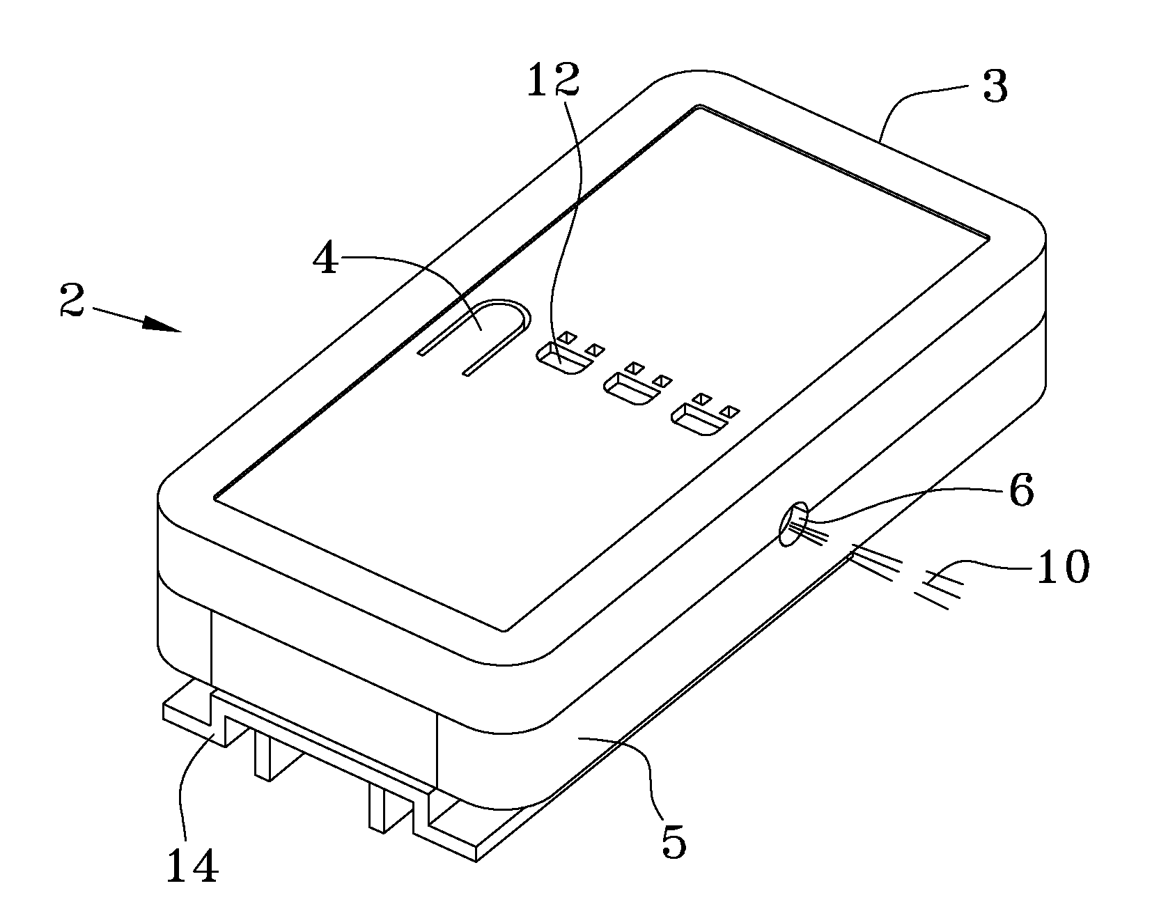
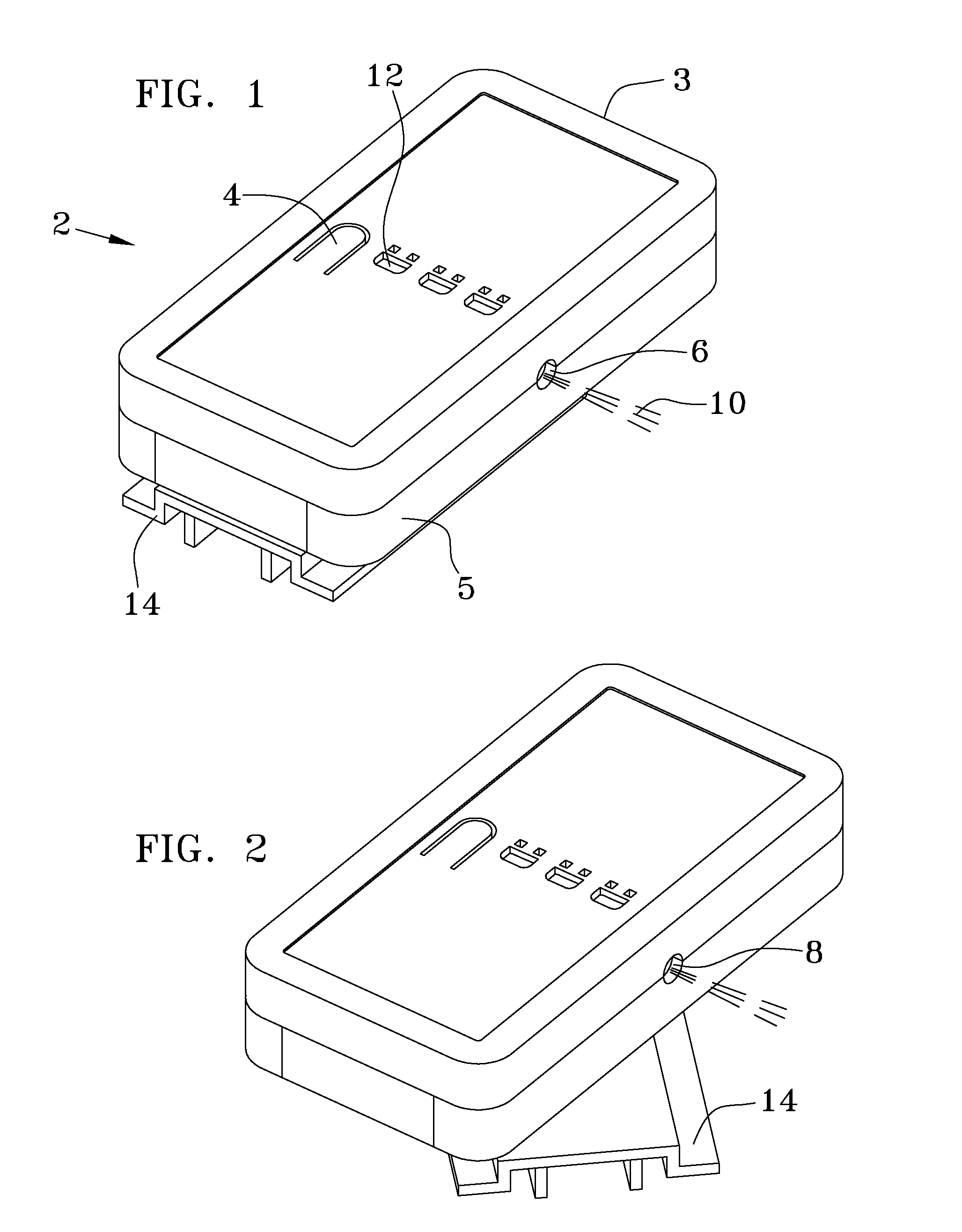
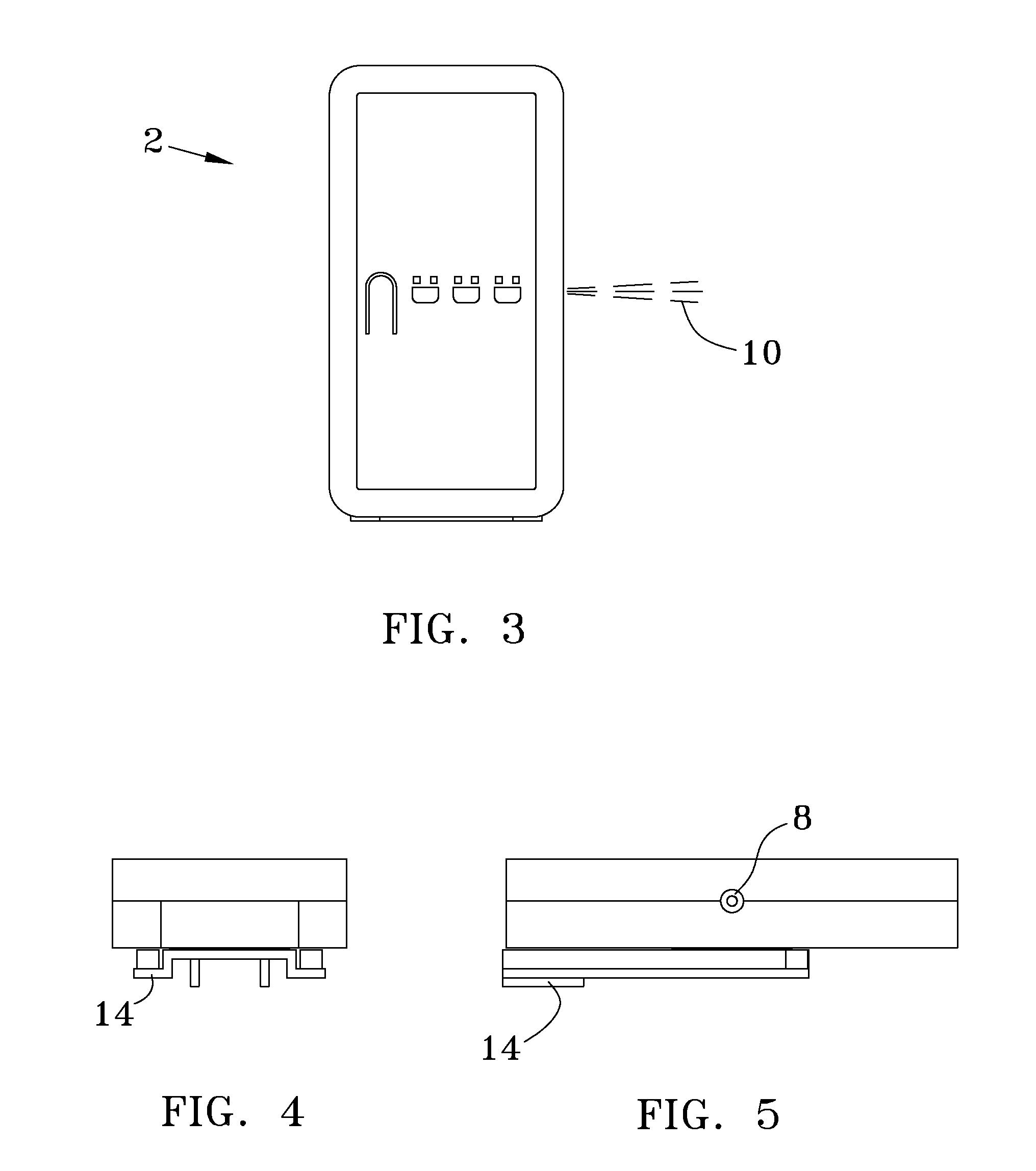
[0005]The general purpose of the present invention, which will be described subsequently in greater detail, is to provide a laser device for the accurate and precise alignment of medical devices to a specific point on the patient's body.
[0012]It is yet a further object of this invention to provide a compact, reliable medical laser alignment system that has programable accuracy, power saving features, a low battery alarm and which can be programmed such that the zero reference point of its triaxial accelerometer may be set to calibrate the laser light beam for a plethora of angles with respect to the horizontal.

Problems solved by technology

The battery life of these devices is generally short as the laser light's power output far exceeds what is actually needed for short range leveling.
Further these early devices are susceptible to loss of accuracy by the initial calibration process, the eye of the user, the illumination of the room and from sharp impacts.
Additionally, the connection of these devices to the vast array of different medical suppliers equipment and supports is problematic.
Lastly, many of the prior art leveling systems are not designed to be used on either side of the patient and cannot be recalibrated.
None of the existing prior art systems allow for angular use such as would be helpful for the specific angular alignment of patient's anatomy while they go through an X-ray machine, and MRI scanner or a CAT scanner.

Method used


Image

  • Microprocessor Controlled Medical Laser Device
  • Microprocessor Controlled Medical Laser Device
  • Microprocessor Controlled Medical Laser Device

Examples


Embodiment Construction

[0024]There has thus been outlined, rather broadly, the more important features of the invention in order that the detailed description thereof that follows may be better understood and in order that the present contribution to the art may be better appreciated. There are, of course, additional features of the invention that will be described hereinafter and which will form the subject matter of the claims appended hereto.

[0025]In this respect, before explaining at least one embodiment of the invention in detail, it is to be understood that the invention is not limited in its application to the details of construction and to the arrangements of the components set forth in the following description or illustrated in the drawings. The invention is capable of other embodiments and of being practiced and carried out in various ways. Also, it is to be understood that the phraseology and terminology employed herein are for the purpose of descriptions and should not be regarded as limiting...


PUM


Abstract

A microprocessor controlled medical laser device that has a precise laser beam alignment system indicated by a series of sequentially color changing LEDS. The power management system adjusts the LED'S power input so as maximize battery life, increasing it by up to six times. It's alignment is enabled by a triaxial accelerometer that may be accurately calibrated horizontally or to a plethora of angles relative to the horizontal axis. It is shock resistant and times out to turn the laser off after a predetermined time.

Description

BACKGROUND OF THE INVENTION[0001]The present invention relates to a laser device that will enable the precise vertical positioning of a plethora of medical sensors, drainage systems, intubation systems, intravenous devices, catheters and the like with respect to a specific point on the patient's anatomy. This specific point may be the heart, the brain, a PIC line insertion point, or a drainage line insertion point.[0002]Precise measurement of a patients vital statistics is critical with very small changes in pressure due to elevation, often having dramatic effects of drainage or supply rates, monitored pressures, static pressure scales, etc. The accurate positioning of the related sensors, scales, fluid lines and the such with respect to elevation the patient's body has heretofore been done with laser beams coupled to crude leveling devices. The battery life of these devices is generally short as the laser light's power output far exceeds what is actually needed for short range leve...

Claims


Application Information

Patent Timeline
IPC IPC(8): A61N5/06
CPCA61B2019/202A61B19/201A61B90/13A61B90/11
Inventor POTTS, RICHARD ALLENPOTTS, LARRY RAY
Owner POTTS RICHARD ALLEN
Learn More