Stand for imaging

a technology for standing and imaging, applied in the field of standing for imaging, can solve the problems of negative effect of image recording quality, the ultrasonic head moves around the ball-and-socket joint support, etc., and achieve the effect of improving image recording

Inactive Publication Date: 2013-04-23
SIEMENS HEALTHCARE GMBH
View PDF9 Cites 7 Cited by
  • Summary
  • Abstract
  • Description
  • Claims
  • Application Information

AI Technical Summary

Benefits of technology

[0005]The present embodiments may obviate one or more of the drawbacks or limitations in the related art. For example, in one embodiment, a stand may improve image recording.
[0007]In one embodiment, the stand may allow, as a result of the ball-and-socket joint support of the imaging device, an accurate and precise alignment of the ultrasound head relative to the imaging area, and provide, as a result of the ability to lock any given position of the ultrasound head adopted relative to the arm, a system for fixing this optimum position for the subsequent imaging. Accordingly, the doctor merely needs to exert the required pressure against the body under investigation. There is no longer any danger of the relative position of the ultrasound head being changed by a movement of the ball joint, since this movable link is fixed or locked using the locking device of one of the present embodiments. Accordingly, the alignment during imaging is no longer changeable.
[0008]The locking device may include or is a clamping device, which clamps the ball head into the head support. Once a user (e.g., the doctor) has made the alignment, the user merely actuates the locking device, which directly results in the clamping of the movable parts in relation to each other, thereby fixing the alignment. For clamp locking, the locking device may include a clamping element able to be moved linearly via a motorized positioning element that, on actuation of the positioning element, is able to be moved against the ball head, pressing the ball head against the head support. The use of a motorized adjustment element for moving the clamping element allows an automated locking. The doctor only has to give a corresponding electrical actuation signal to the locking device or to the motorized adjustment element (e.g., through a suitable control key that the user holds, or the like in the area of the imaging device), in order to control an adjusting motor, which then moves the clamping element into the clamping position. The clamping element may be a clamping sleeve and may include a pressure surface adapted to the shape of the ball head, which presses against and clamps the ball head. This enables a large clamping surface to be realized, which makes clamping that is secure, by virtue of being a high-force and a form-fit clamping, possible.
[0010]In one embodiment, the clamping element may be held pre-tensioned via at least one tensioning element (e.g., a coil spring) against the ball head. In other words, even when the strain on the clamping element is removed and there is no clamping, the clamping element may be in slight contact with the ball head, allowing the ball head to move but preventing movement of the clamping element that could lead to noises. In one embodiment, the sleeve or nut may loosely engage the clamping element or the clamping sleeve, respectively.

Problems solved by technology

The doctor may press the ultrasound head during the entire imaging process with considerable pressure against the breast; this requires great effort on the part of the doctor and results in the problem that the ultrasound head moves around the ball-and-socket joint support, either as a result of the breathing movement of the patient or the movement of the doctor.
Such a change in the relative position of the ultrasound head to the imaging area has a negative effect on the quality of the images recorded.

Method used


Image

  • Stand for imaging
  • Stand for imaging
  • Stand for imaging

Examples


Embodiment Construction

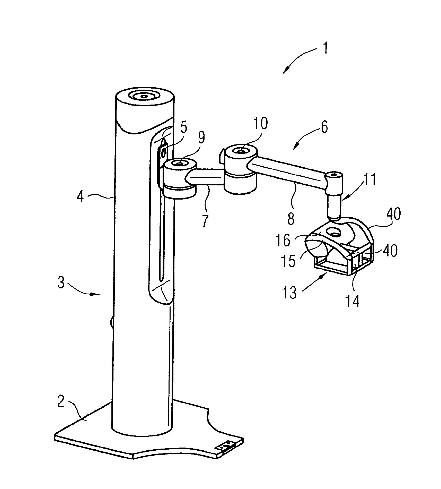
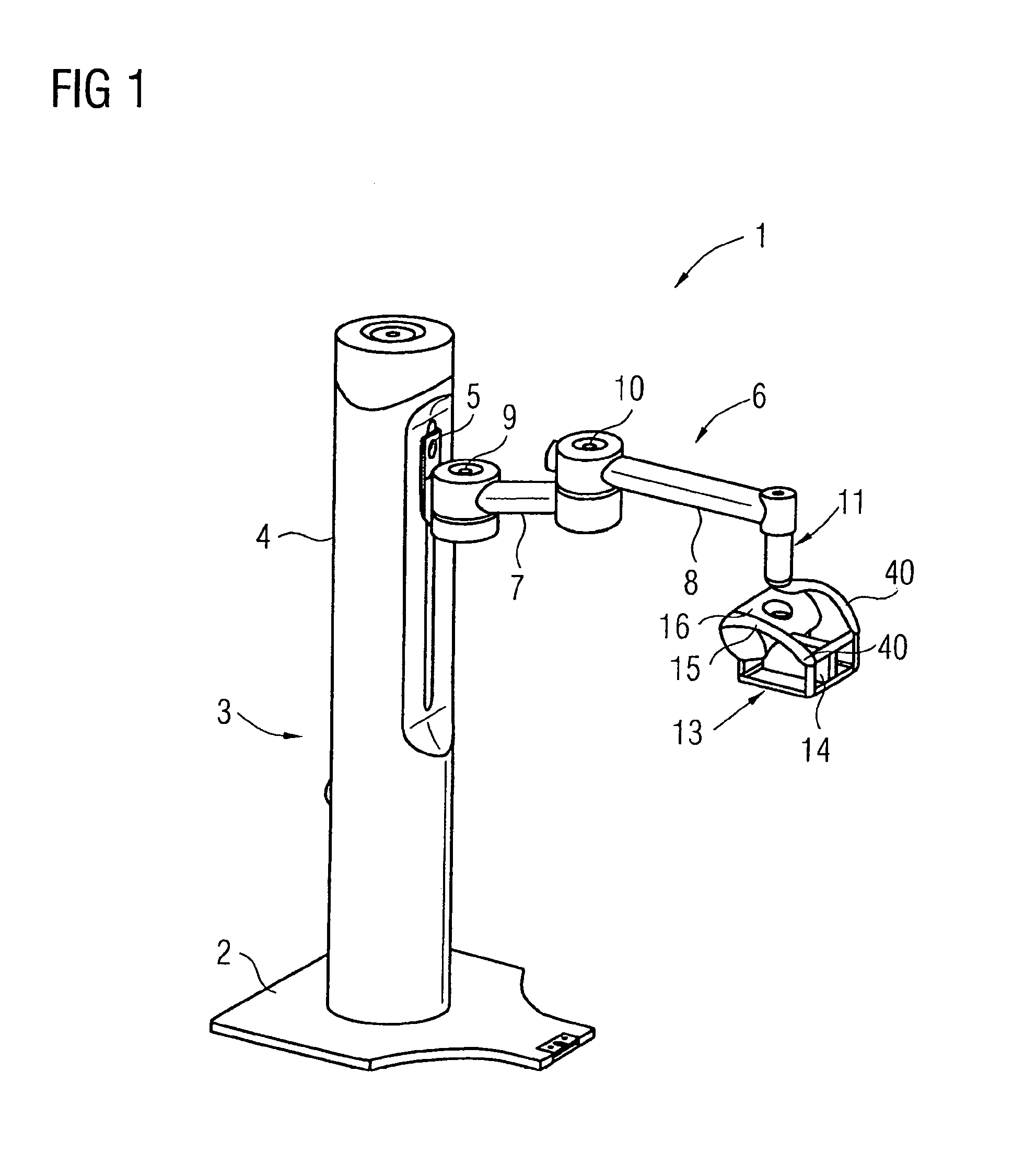
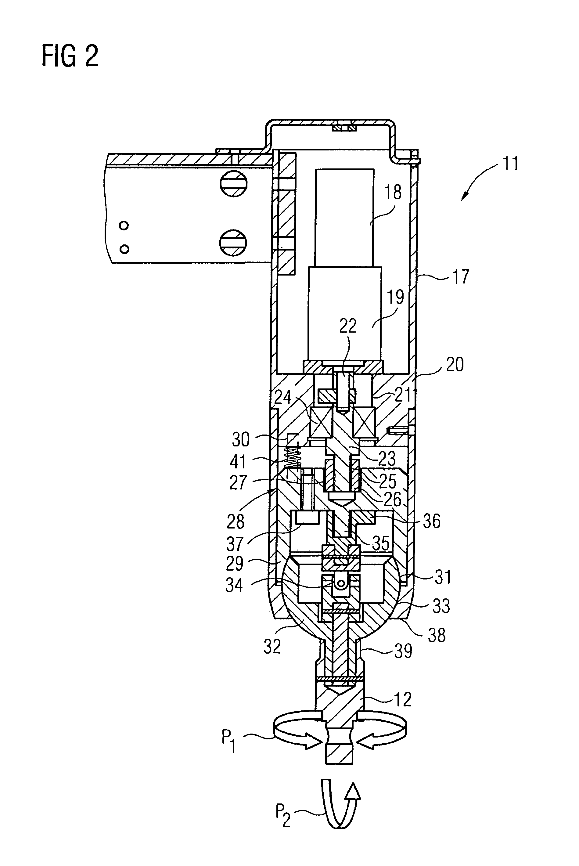
[0017]FIG. 1 shows an embodiment of a stand 1 with a floor plate 2, on which a vertical pillar 3 with a casing 4 is arranged. Guided vertically on the vertical pillar 3 via a linear guide (e.g., rail and guide carriage) to allow a vertical movement is an arm 6 comprising two arm sections 7, 8. The arm 6 is pivotable via a first pivot 9 relative to the linear guide 5. A second pivot point 10 between the arm sections 7 and 8 allows the two arm sections 7 and 8 to pivot relative to one another. An adapter 11, on which an attachment section shown in FIG. 2 is provided, is located at an end of the arm section 8. An imaging device 13, (e.g., an ultrasound head 14 for recording ultrasound images during the course of a mammography) can be detachably fastened to the adapter 11. The imaging device 13 may include a frame-type housing 15, on which a section 16 with diverse operating devices (e.g., pivot motor, control system) is provided, and the pivotable ultrasound head 14. The imaging device...


PUM


Abstract

A stand, especially a floor stand, with a movable arm with an attachment section provided at the end of the arm for an object to be held by means of the stand, especially an imaging device in the form of an ultrasound head, with the attachment section being supported movably on the arm via a ball-and-socket joint comprising a ball head carrying the attachment section and a head holder supporting the ball head on the arm side, with a locking device being provided for releasable locking of the ball head (32) in its adopted position in the head holder.

Description

[0001]This application claims the benefit of DE 10 2008 059 344.3 filed Nov. 27, 2008, which is hereby incorporated by reference.BACKGROUND[0002]The present embodiments relate to a stand with a movable arm and an attachment section provided on the end of the arm for an object to be held by the stand.[0003]Stands are frequently used with a medical imaging apparatus, such as an ultrasound head, and have a movable arm arranged on a vertical pillar on which the imaging apparatus is arranged. The movement capability for the ultrasound head is provided by the movability of the arm and also by a ball-and-socket joint support of the imaging apparatus on the arm. In practice, the imaging apparatus, for example the ultrasound head (the imaging apparatus is to be taken as including larger systems or components, for example, including a frame or the like), is applied and positioned by the doctor on a patient, for example, to record an image of a breast in a mammography. The doctor aligns the ul...

Claims


Application Information

Patent Timeline
Patent Type & Authority Patents(United States)
IPC IPC(8): F16M13/00
CPCA61B8/0825A61B8/4218A61B19/26F16M11/04F16M11/14F16M11/2014F16M11/24A61B17/2255A61B2019/264Y10T403/32196A61B2019/266A61B2090/504A61B90/50A61B2090/508
Inventor FADLER, FRANZWEIDNER, PAULPANDA, SATCHI
Owner SIEMENS HEALTHCARE GMBH
Why Eureka
Try Eureka