Optical pickup and information equipment

a technology of information equipment and optical pickups, applied in the field of optical pickups, can solve the problem that the configuration disclosed in the patent document 1 cannot be realized, and achieve the effect of increasing the degree of design freedom

Inactive Publication Date: 2011-02-22
PIONEER CORP
View PDF8 Cites 2 Cited by
  • Summary
  • Abstract
  • Description
  • Claims
  • Application Information

AI Technical Summary

Benefits of technology

[0006]In view of the aforementioned conventional problems, it is therefore an object of the present invention to provide an optical pickup and information equipment which can increase the degree of freedom in design while preferably controlling the light intensity of the laser beam.Means for Solving the Subject

Problems solved by technology

Namely, it has such a technical problem that the configuration disclosed in the patent document 1 cannot be realized in some cases due to the spatial limitation of the optical disc apparatus or the like.

Method used


Image

  • Optical pickup and information equipment
  • Optical pickup and information equipment
  • Optical pickup and information equipment

Examples


examples

[0066]Hereinafter, the examples of the present invention will be explained on the basis of the drawings.

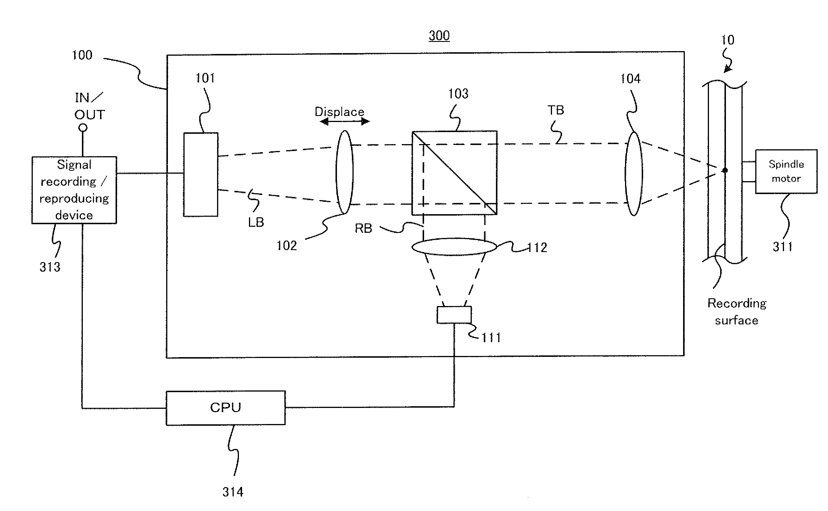
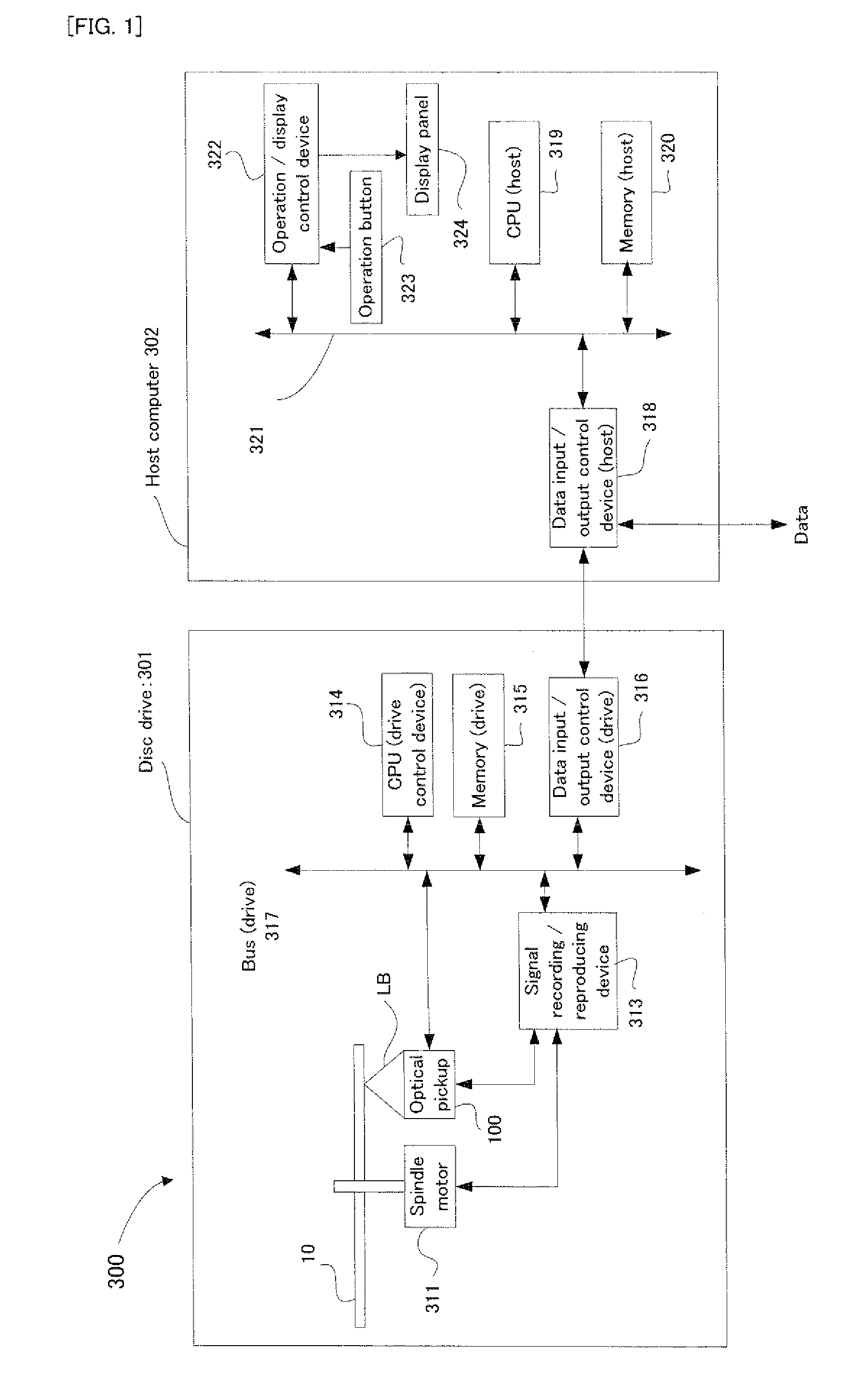
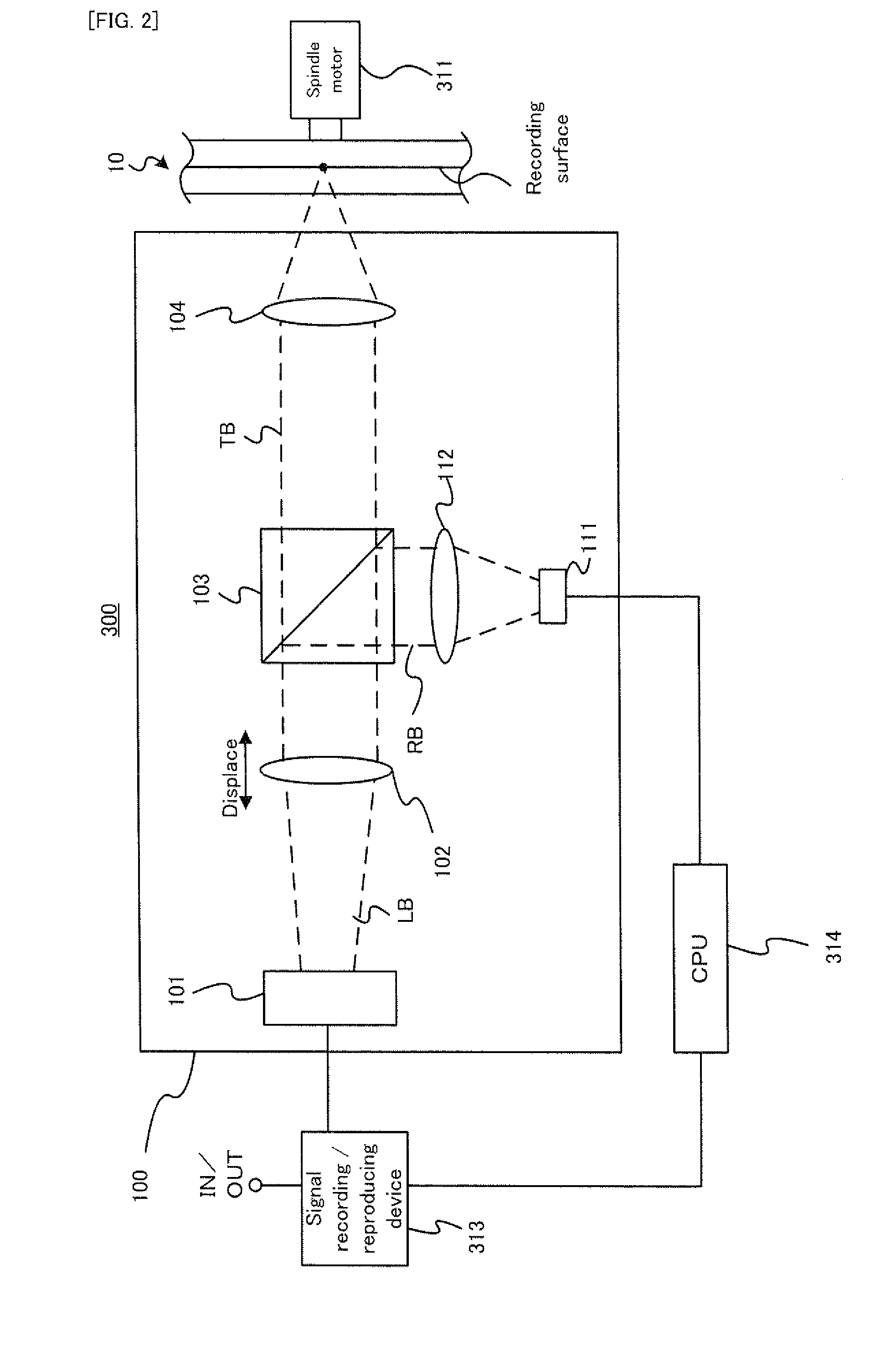
[0067]Firstly, with reference to FIG. 1, an explanation will be given on the basic structure of an information recording / reproducing apparatus (i.e. an example of the information equipment of the present invention) provided with an example of the optical pickup apparatus of the present invention. FIG. 1 is a block diagram schematically showing the general structure of an information recording / reproducing apparatus 300 provided with an optical pickup 100 in this example. Incidentally, the information recording / reproducing apparatus 300 has a function of recording data onto an optical disc 10 and a function of reproducing the data recorded on the optical disc 10.

[0068]As shown in FIG. 1, the information recording / reproducing apparatus 300 is provided with a disc drive 301 on which the optical disc 10 is actually loaded and on which the data recording and the data reproduction are pe...


PUM

PropertyMeasurementUnit
wavelengthaaaaaaaaaa

Abstract

An optical pickup (100) includes: an irradiating device (101) for irradiating a laser beam (LB); a first light focusing device (104) for focusing the laser beam on the recording medium (10); a collimator device (102) which is disposed on the optical path between the irradiating device and the first light focusing device and which can be displaced along the optical path of the laser beam; a splitting device (103) which reflects one portion of the laser beam and transmits therethrough another portion of the laser beam; a light receiving device (111) for receiving the reflected one portion of the laser beam; and a second light focusing device (112) for focusing, on the light receiving device, the reflected one portion of the laser beam, the light receiving device and the first light focusing device is disposed at a position at which rate of change in light density of the laser beam on the first light focusing device before and after displacement of the collimator device is substantially the same as that on the light receiving device before and after the displacement of the collimator device.

Description

[0001]This application is a 371 of PCT / JP2006 / 319599, filed Sep. 29, 2006.TECHNICAL FIELD[0002]The present invention relates to an optical pickup for irradiating an optical disc with a laser beam, and information equipment provided with the optical pickup.BACKGROUND ART[0003]For example, like a CD and a DVD, an optical disc for optically recording or reproducing data using a laser beam or the like has been developed. In such an optical disc, there may be variation in substrate thickness. The variation in substrate thickness leads to the occurrence of spherical aberration. Therefore, in order to perform preferable recording and reproducing operations, it is necessary to reduce the influence of the spherical aberration caused by the variation in substrate thickness. One method developed for this purpose is a method of focusing the laser beam on a recording surface in accordance with the variation in substance thickness by changing the position of a collimator lens (or a condenser lens...

Claims


Application Information

Patent Timeline
Patent Type & Authority Patents(United States)
IPC IPC(8): G11B7/00G11B7/125G11B7/135
CPCG11B7/1263G11B7/1356G11B7/1376G11B7/13927G11B7/0948
Inventor KAWAMURA, MAKOTO
Owner PIONEER CORP
Why Eureka
Try Eureka