
Multi-function printer with a locking device and operational method thereof

a multi-function printer and locking device technology, applied in the direction of digital output to print units, instruments, electrographic processes, etc., can solve the problems of user injury or damage to the multi-function printer, multi-function printer has no security mechanism to ensure the user's operation security and convenience, etc., to prevent user danger

Inactive Publication Date: 2011-02-22
LITE ON TECH CORP
View PDF6 Cites 12 Cited by
  • Summary
  • Abstract
  • Description
  • Claims
  • Application Information

AI Technical Summary

Benefits of technology

[0007]The invention is directed to a multi-function printer with a locking device and operational method thereof. The locking device, formed by simple movement pieces, serves as a security mechanism to ensure the user's operational security and convenience and prevent the user's danger and machine damage from being occurred due to operational neglect.

Problems solved by technology

However, due to consideration of small-size appearance and manufacturing cost, the present multi-function printer has no security mechanism to ensure the user's operational security and convenience.
Therefore, the user may be injured or damage the multi-function printer due to his / her operation neglect.

Method used


Image

  • Multi-function printer with a locking device and operational method thereof
  • Multi-function printer with a locking device and operational method thereof
  • Multi-function printer with a locking device and operational method thereof

Examples


Embodiment Construction

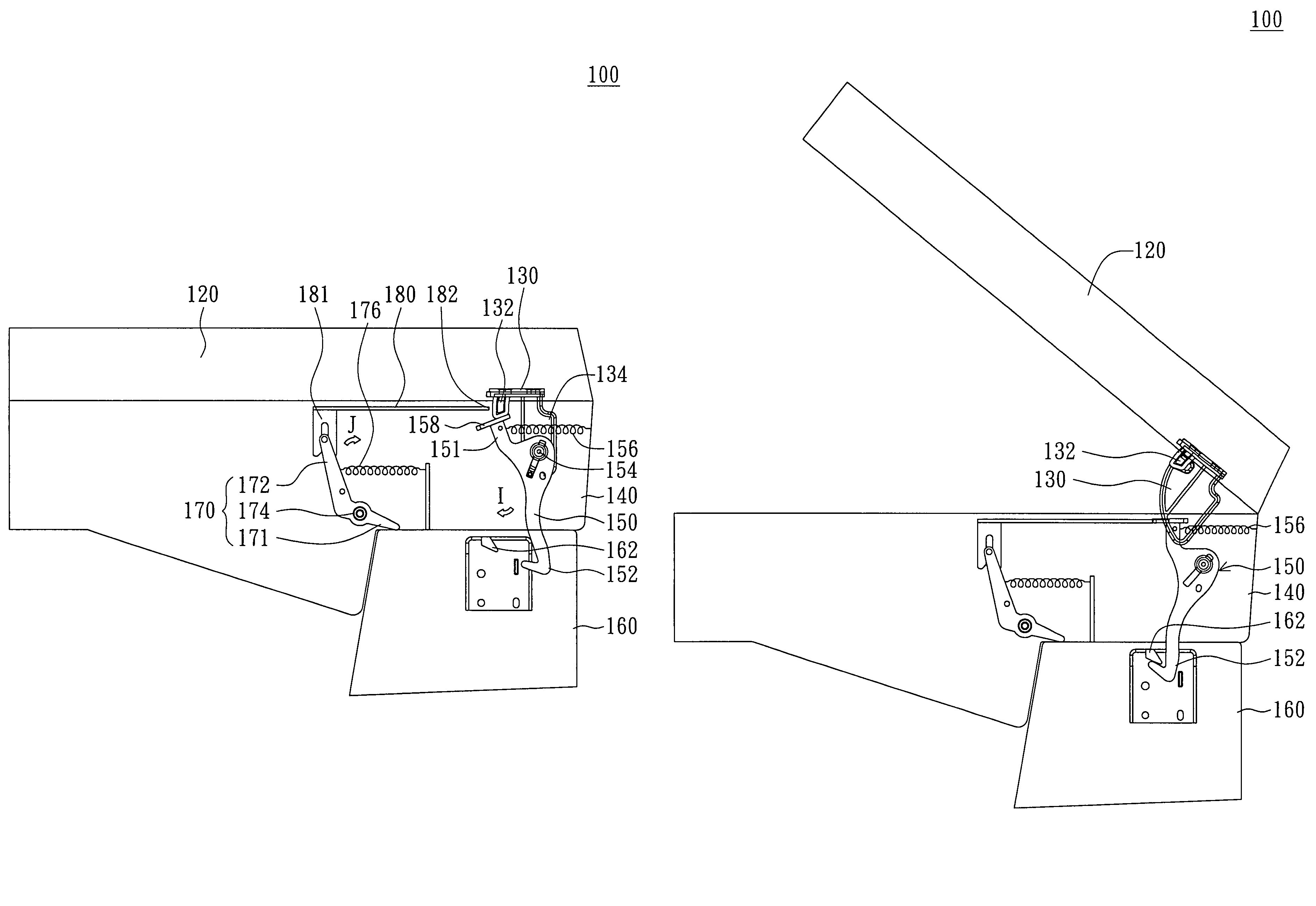
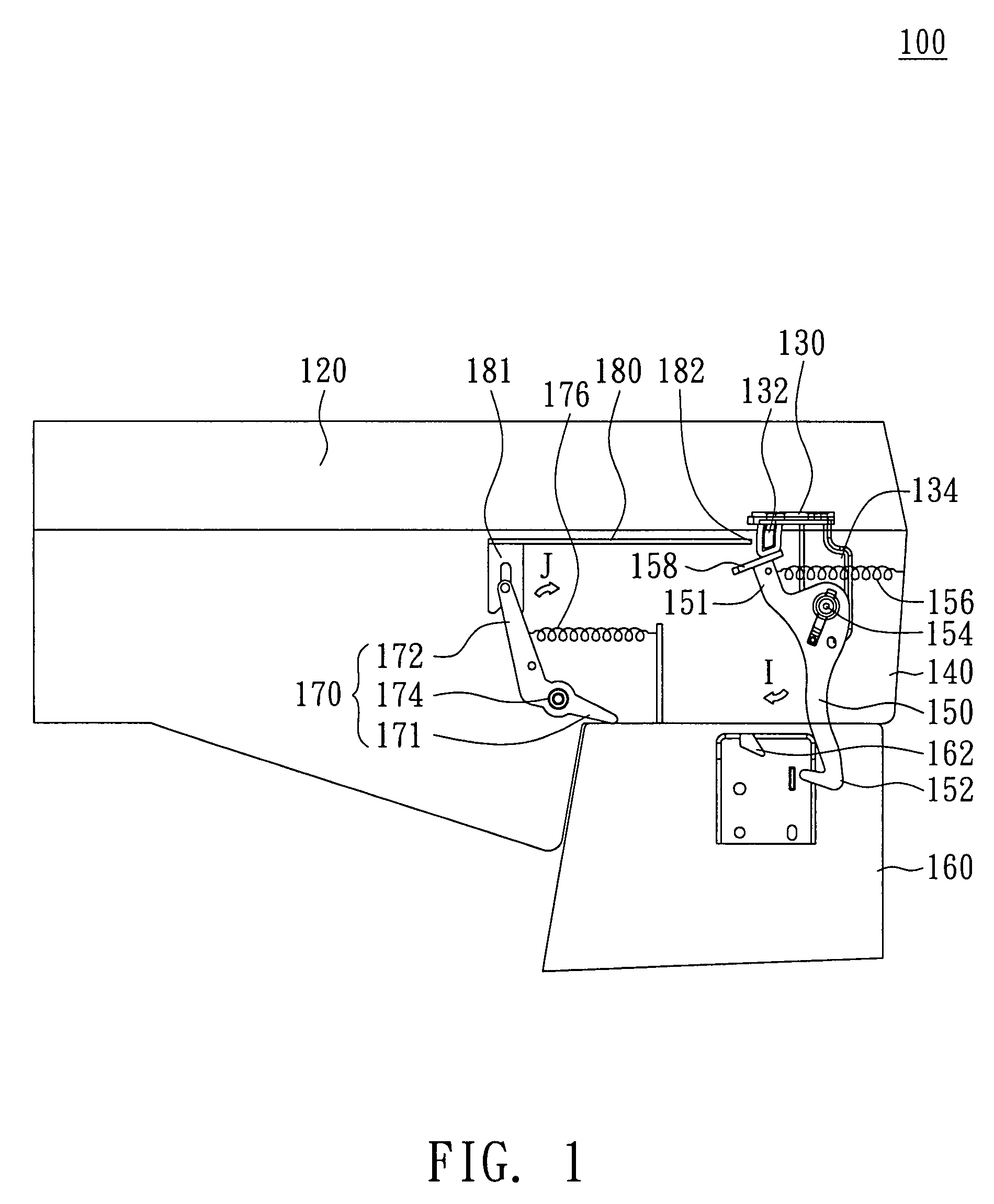
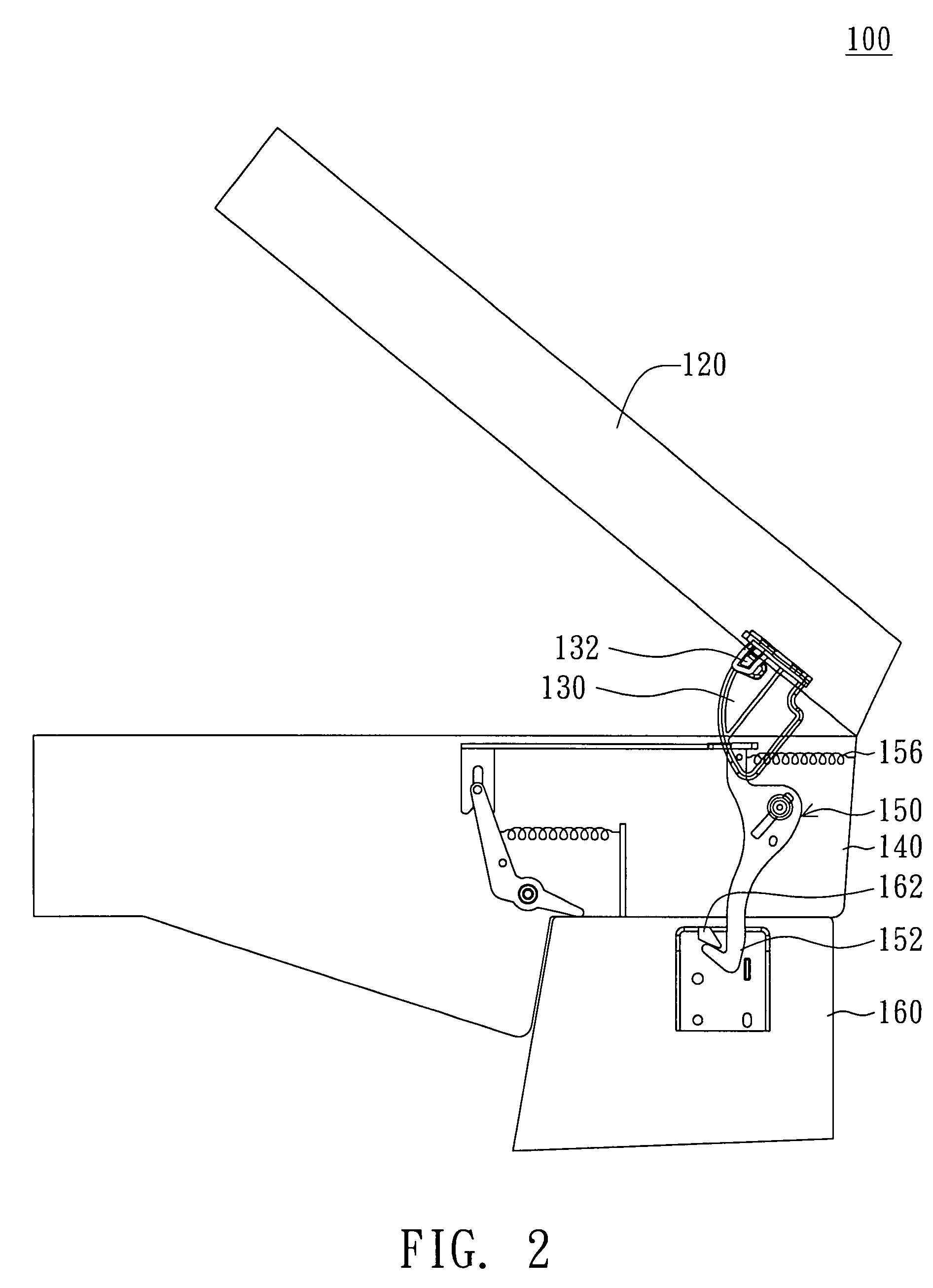
[0015]Referring to FIG. 1, a lateral view of a multi-function printer with a first module, a second module and a third module stacked successively according to a preferred embodiment of the invention is shown. The multi-function printer 100 of the embodiment includes a first module 120, a second module 140, a third module 160, a trigger piece 130, a wedging piece 150, an actuating piece 170 and a join piece 180. For example, the first module 120 is an ADF, the second module 140 is a scanner and the third module 160 is a main body. The second module 140 is disposed under the first module 120 and pivotally connected to the first module 120. The third module 160 is disposed under the second module 140 and pivotally connected to the second module 140. The moving pieces including the trigger piece 130, wedging piece 150, actuating piece 170 and join piece 180 have a connection relationship in accordance with the relative connection status of the first module 120, the second module 140 an...


PUM


Abstract

A multi-function printer is provided. A trigger piece is fixed to the first module and stretched into a second module. A wedging piece is disposed in the second module and protruded from the second module. An actuating piece and a join piece are disposed in the second module. The actuating piece has a first end connected to the actuating piece and a second end positioned close to the trigger piece. When the three modules are stacked together, the trigger piece goes against the wedging piece and the actuating piece goes against a third module. When the first module is rotated, the trigger piece is separated from the wedging piece such that the wedging piece can be wedge with the third module. When the second module is rotated, the actuating piece drives the joint piece to wedge with the trigger piece.

Description

[0001]This application claims the benefit of Taiwan application Serial No. 095223034, filed Dec. 28, 2006, the subject matter of which is incorporated herein by reference.BACKGROUND OF THE INVENTION[0002]1. Field of the Invention[0003]The invention relates in general to a multi-function printer and operational method thereof and more particularly to a multi-function printer with a locking device and operational method thereof.[0004]2. Description of the Related Art[0005]A multi-function printer (MFP) includes an auto document feeder (ADF), a flat-bed scanner and a print machine. For usage convenience, the conventional multi-function printer has a number of cover lifting designs. For example, the flat-bed scanner includes a movable upper cover normally combined with a thick and heavy ADF and the user has to open the upper cover before putting a to-be-scanned document on the flat-bed. Besides, owing that the print machine is normally positioned at a lower part of the multi-function pr...

Claims


Application Information

Patent Timeline
Patent Type & Authority Patents(United States)
IPC IPC(8): G03G21/00G03G15/00B41J29/00
CPCH04N1/00554H04N1/00519
Inventor SU, CHIUNG-YIHSU, MING-HUNGLIU, CHIN-CHIA
Owner LITE ON TECH CORP
Learn More