

Sample holder for holding samples at pre-determined angles
a pre-determined angle and sample technology, applied in the field ofatomic resolution imaging, can solve the problems of inaccuracy of afm that is not properly characterized, and achieve the effect of avoiding inaccuracy and avoiding inaccuracy
- Summary
- Abstract
- Description
- Claims
- Application Information
AI Technical Summary
Benefits of technology
Problems solved by technology
Method used
Image

Examples
Embodiment Construction
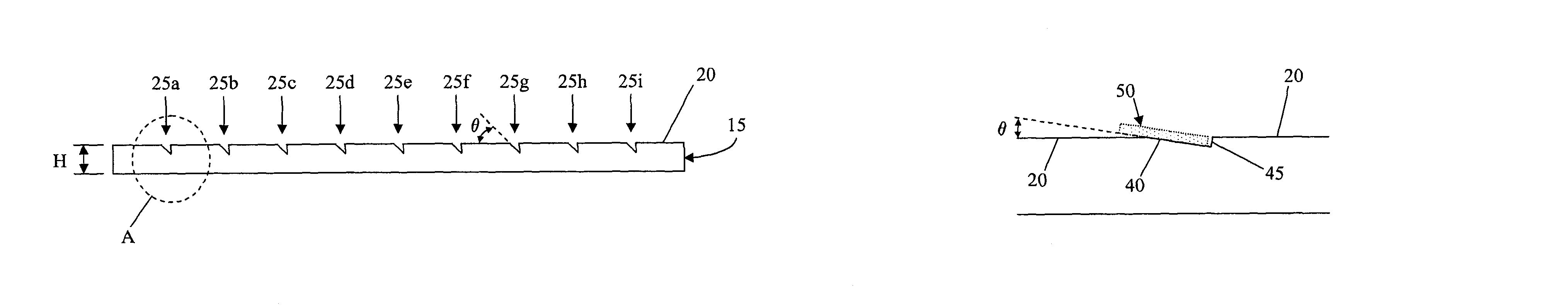
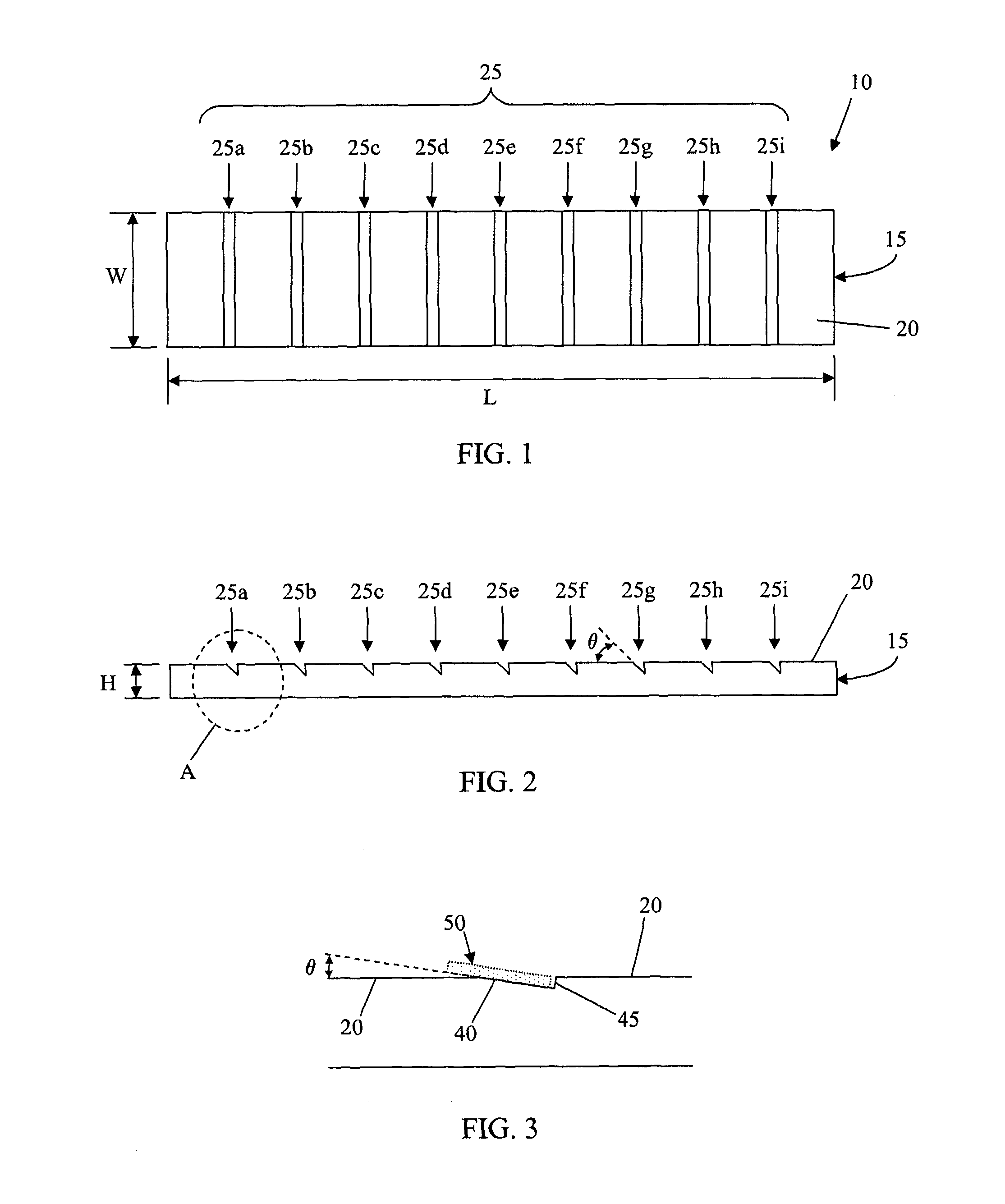
The invention generally relates to atomic resolution imaging, and, more particularly, to systems and methods for characterizing an atomic resolution measurement tool. Exemplary embodiments of the invention include a sample holder having multiple angled slots formed in a surface to hold test samples. The sample holder allows a user to choose any one of multiple angled slots to place test samples with great accuracy as to the known angle of the slot (and, therefore, the test sample). Aspects of the invention thus allow a user to precisely locate a test sample with respect to an imaging device (e.g., an atomic force microscope), such that the imaging device can be accurately characterized.
FIG. 1 shows a sample holder 10 according to aspects of the invention. In embodiments, the sample holder includes a block 15 (e.g., a chuck) having a top surface 20. Formed in the top surface 20 are a plurality of inclined regions 25 (e.g., 25a-25i shown in FIG. 1). For example, the block 15 may be co...
PUM
 Abstract
Description
Claims
Application Information