Integral bonding attachment

a technology of integrated bonding and attachment, which is applied in the direction of connection insulation, multi-conductor cable end pieces, coupling device connections, etc., can solve the problems of conductor cable breakage, conductor cable breakage, and less than optimal performan

Active Publication Date: 2011-03-01
CARLISLE INTERCONNECT TECH
View PDF68 Cites 38 Cited by
  • Summary
  • Abstract
  • Description
  • Claims
  • Application Information

AI Technical Summary

Problems solved by technology

First, a weakness exists between the conductor cable and the open end or sleeve of the lug.
Furthermore, the stress on the conductor at the crimp might cause the conductor to break at that point.
Additionally, potential for less than optimal performance exists.
Oftentimes, the lug is made of a different metal than the conductor and corrosion may occur between the dissimilar metals.
Furthermore, the lug-to-cable interface is often subject to corrosion due to moisture.
This may lead to premature corrosion failure of the cable.
Also, the crimped lug may not provide a good low resistance or low impedance path through the end of the conductor.
As may be appreciated, such additional steps are time consuming and costly.
Also, as may be appreciated, it is undesirable to provide a break or cut in the length of the cable.

Method used


Image

  • Integral bonding attachment
  • Integral bonding attachment
  • Integral bonding attachment

Examples


Embodiment Construction

[0032]The descriptions contained here are meant to be understood in conjunction with the drawings that have been provided.

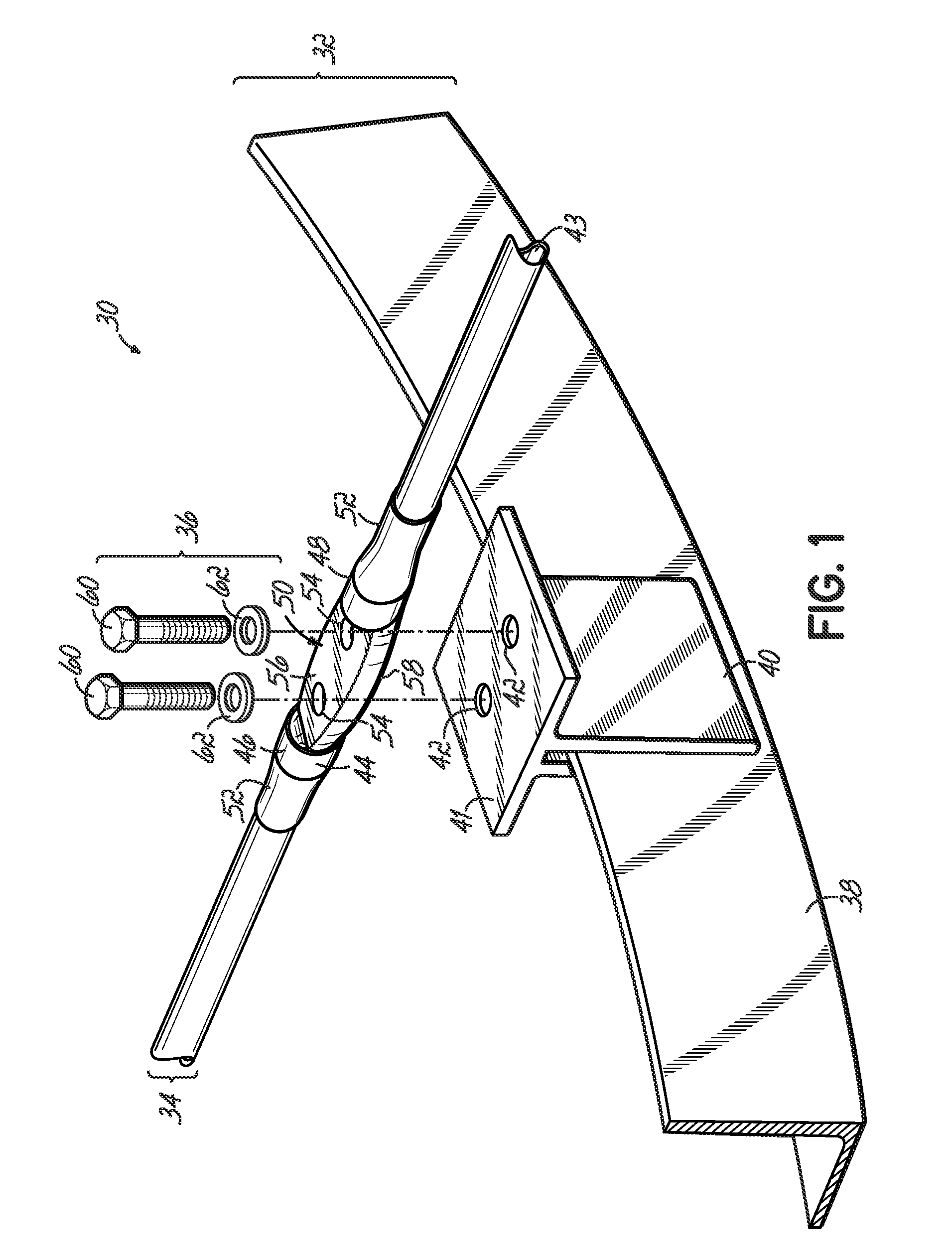
[0033]FIG. 1 illustrates an assembly 30 utilizing an embodiment of the invention. The exemplary assembly 30 shown in FIG. 1 generally includes three portions or elements. The first portion is an attachment portion or element 32. The attachment portion 32 is a structure or element or frame with a substantially suitable surface to which the integral bonding attachment 34 of the invention is attached. In one exemplary assembly, the attachment portion has a flat surface to receive the integral bonding attachment 34. The second portion is the integral bonding attachment 34, embodiments of which are disclosed herein. The integral bonding attachment 34 of the invention utilizes includes a portion of a conductive element or conductor, such as a conductive wire or cable 43 and a sleeve or barrel 44. The portion of the wire 43 is shown in FIG. 1, but it will be understood ...


PUM


Abstract

An integral bonding attachment includes an insulated section of a conductive wire with an exposed, uninsulated section. A sleeve covers the insulated and uninsulated sections of the conductive wire, and the sleeve includes a flattened section encasing at least a portion of the uninsulated wire section to form a generally integral structure with the core of the conductive wire. At least one generally tubular section is positioned at an end of the flattened section to engage the insulated section of the conductive wire. An aperture may pass simultaneously through the inner core and flattened sleeve section for attaching the integral bonding attachment to a structure.

Description

RELATED APPLICATIONS[0001]This application is a continuation-in-part application of U.S. patent application Ser. No. 11 / 315,456 filed Dec. 22, 2005 and entitled “Integral Bonding Attachment”, which application is completely incorporated herein by reference.TECHNICAL FIELD OF THE INVENTION[0002]The present invention is directed to devices for connecting and securing a conductor or wire to a support structure, and particularly, but not exclusively, to an integral bonding attachment for connecting a conductive wire to a support surface in the construction of an aircraft.BACKGROUND OF THE INVENTION[0003]During the construction of many different structures, such as airplanes, it is necessary to provide suitable grounding for the electronics and electrical systems. It is particularly critical for airplane construction, because airplanes, in addition to requiring a robust ground reference for their electrical systems, are also subject to outside electrical phenomenon, such as lighting and ...

Claims


Application Information

Patent Timeline
Patent Type & Authority Patents(United States)
IPC IPC(8): H01R4/18
CPCH01R4/20H01R13/5216H01R4/70Y10S439/932H01R11/12
Inventor CECIL, DAVID CHARLESSUTHERLAND, JACK EDGAR
Owner CARLISLE INTERCONNECT TECH
Why Eureka
Try Eureka