Display device, data driver IC, and timing controller

a timing controller and data driver technology, applied in the field of timing controllers, can solve the problems of increasing power consumption and emi, unable to change the characteristics of lut and dac after preparing a chip, and high shift frequency, so as to reduce the bus width between the timing control unit and the data line driving circuit, and reduce the amount of data transmission

Inactive Publication Date: 2011-03-01
RENESAS ELECTRONICS CORP
View PDF10 Cites 0 Cited by
  • Summary
  • Abstract
  • Description
  • Claims
  • Application Information

AI Technical Summary

Benefits of technology

[0012]In the display device according to the present invention, a gamma correction, which is optimal to characteristics of the display panel, can be executed by changing the conversion parameter. The data transmission amount between the timing control unit and the data line driving circuit can be reduced in comparison with a display device in which a LUT is included in a timing control unit. Therefore, in the case that the input gradation signal supplied from the timing control unit is parallel data, a bus width between the timing control unit and the data line driving circuit can be reduced. In the case that the input gradation signal is serial data, the shift frequency generated among the input gradation signals can be reduced.

Problems solved by technology

In the case of a serial transmission, the number of bit for the serial transmission is also increased, which results in high shift frequency.
In the case of serial transmission, shift frequency becomes higher that causes the increase in power consumption and EMI.
Furthermore, it is impossible to change characteristics of the LUT and DAC after preparing a chip.
Therefore, in the case of causing a difference between the characteristics of a liquid crystal panel and that stored in the chip, particularly a difference with respect to characteristics (correction curves) that are made different in the respective colors (RGB) as shown in FIG. 1A, a fine adjustment can not be allowed for correcting the difference.

Method used


Image

  • Display device, data driver IC, and timing controller
  • Display device, data driver IC, and timing controller
  • Display device, data driver IC, and timing controller

Examples


first embodiment

1. First Embodiment

[0030]FIG. 3 is a block diagram showing a configuration of a liquid crystal display device according to the first embodiment of the present invention. Referring to FIG. 3, the liquid crystal display device according to the present invention includes a liquid crystal panel 1, a data line driving circuit 2, a scanning line driving circuit 3, a timing control unit (TCON) 4, a parameter output unit 5, and a gradation voltage generating circuit (not shown). On the liquid crystal panel 1, there are provided a plurality of data lines (here, 3n number of data lines) arranged in the column direction, a plurality of scanning lines (here, m number of scanning lines) arranged in the row direction, and pixels including a TFT and a liquid crystal capacity arranged in regions where the data lines are crossed with the scanning lines. A gate electrode of the TFT in each of the pixels on the liquid crystal panel 1 is connected to one of the scanning lines, and a drain electrode of ...

second embodiment

2. Second Embodiment

[0043]FIG. 5 is a block diagram showing the configuration of a liquid crystal display device according to a second embodiment of the present invention. The liquid crystal display device in the second embodiment includes a TCON 4A provided with a parameter output unit 43 in place of the TCON 4 in the first embodiment, in which the bus 8 for the LUT setting parameter is not provided. Referring to FIG. 5, the TCON 4A in the second embodiment includes a timing output unit 41, a video signal output unit 42 and a parameter output unit 43. The timing control unit 41 outputs a timing control signal 104 to the video signal output unit 42 and the parameter output unit 43 so as to control the video signal output unit 42 and the parameter output unit 43. The video signal output unit 42 includes a memory (not shown), stores a video data Din supplied from an image drawing circuit (not shown) in the memory, and outputs the input gradation signal Dinj of 10 bits to a data line d...

third embodiment

3. Third Embodiment

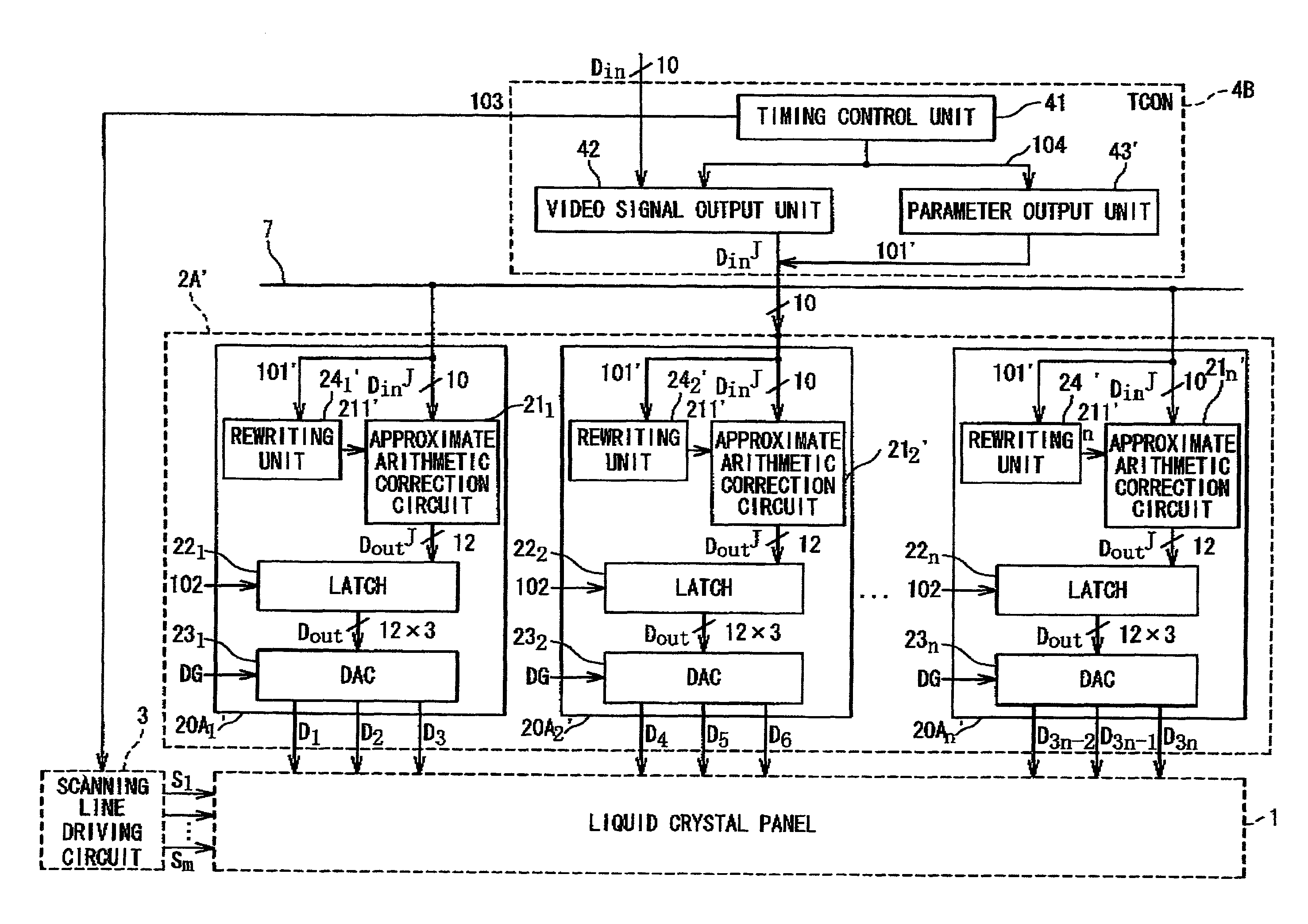
[0046]FIG. 7 is a block diagram showing the configuration of a liquid crystal display device according to a third embodiment of the present invention. This configuration is different from the configuration in the first embodiment in the point that the TCON 4 is connected to the data driver ICs 20l to 20n in one-to-one correspondence by using a bus 7′. That is, referring to FIG. 7, the liquid crystal display device according to the present invention is configured to wire the bus 7′ between the TCON 4 and each of the data driver ICs 20l to 20n in the data line driving circuit 2A in one-to-one correspondence in place of the bus 7 in the first embodiment. Due to this configuration, the TCON 4 is capable of outputting the input video signal Dinj to each of the data driver ICs 20l to 20n simultaneously. Therefore, the data processing time spent for one data driver IC 20 can be extended. In the present embodiment, a configuration of excluding the parameter output 5 and t...


PUM


Abstract

A display device includes a display panel, a data line driving circuit, a timing control unit and a parameter output unit. The data line driving circuit drives data lines on the display panel. The timing control unit outputs an input gradation signal based on an image signal to the data line driving circuit at a predetermined timing. The parameter output unit outputs a conversion parameter for executing gamma correction corresponding to characteristics between a driving voltage and a luminance of the display panel. The data line driving circuit includes: a correction circuit which converts the input gradation signal to an output gradation signal based on the conversion parameter and outputs the converted signal, and a D / A conversion circuit which converts the output gradation signal to a data line driving signal of an analog signal and drive the data lines.

Description

BACKGROUND OF THE INVENTION[0001]1. Field of the Invention[0002]The present invention relates to a display device in which a timing controller, a plurality of data driver ICs, a scanning line driving circuit and a display panel are provided separately. More particularly, the present invention relates to a display device, a data driver and a timing controller for conducting a multi gradation display by a voltage modulation method using a DA converter.[0003]2. Description of the Related Art[0004]Video signals of an image televised in an ordinary television broadcast are transmitted through a γ (gamma) correction which is consistent with IT (current-luminance) characteristics of a cathode ray tube (CRT). Accordingly, in the case of displaying the above video signals as an image in a display device other than the CRT, it is necessary to make a gradation correction (hereinafter referred to as γ correction) corresponding to the characteristics between the driving voltage and the luminance...

Claims


Application Information

Patent Timeline
Patent Type & Authority Patents(United States)
IPC IPC(8): G09G3/36
CPCG09G3/3611G09G3/3688G09G2300/0426G09G2310/0218G09G2310/027G09G2320/0276G09G2320/0673G09G2370/08
Inventor UMEDA, KENGOHORI, YOSHIHIKONOSE, TAKASHIFURIHATA, HIROBUMI
Owner RENESAS ELECTRONICS CORP
Why Eureka
Try Eureka