Breathing circuit

a technology of circuits and breathing tubes, applied in the field of breathing circuits, can solve the problems of inability to trust the medical staff wholly that patients have complied with pre-anesthesia instructions, many challenges, and inherently complex procedures of anesthesia

a technology of circuits and breathing tubes, applied in the field of breathing circuits, can solve the problems of inability to trust the medical staff wholly that patients have complied with pre-anesthesia instructions, many challenges, and inherently complex procedures of anesthesia

US7900633B2Active Publication Date: 2011-03-08SINHA SHAILENDRA K

Image

  • Breathing circuit
  • Breathing circuit
  • Breathing circuit

Examples


Embodiment Construction

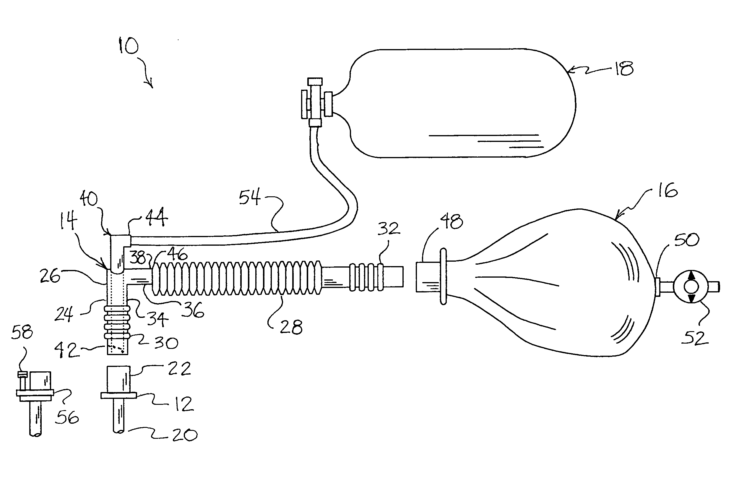
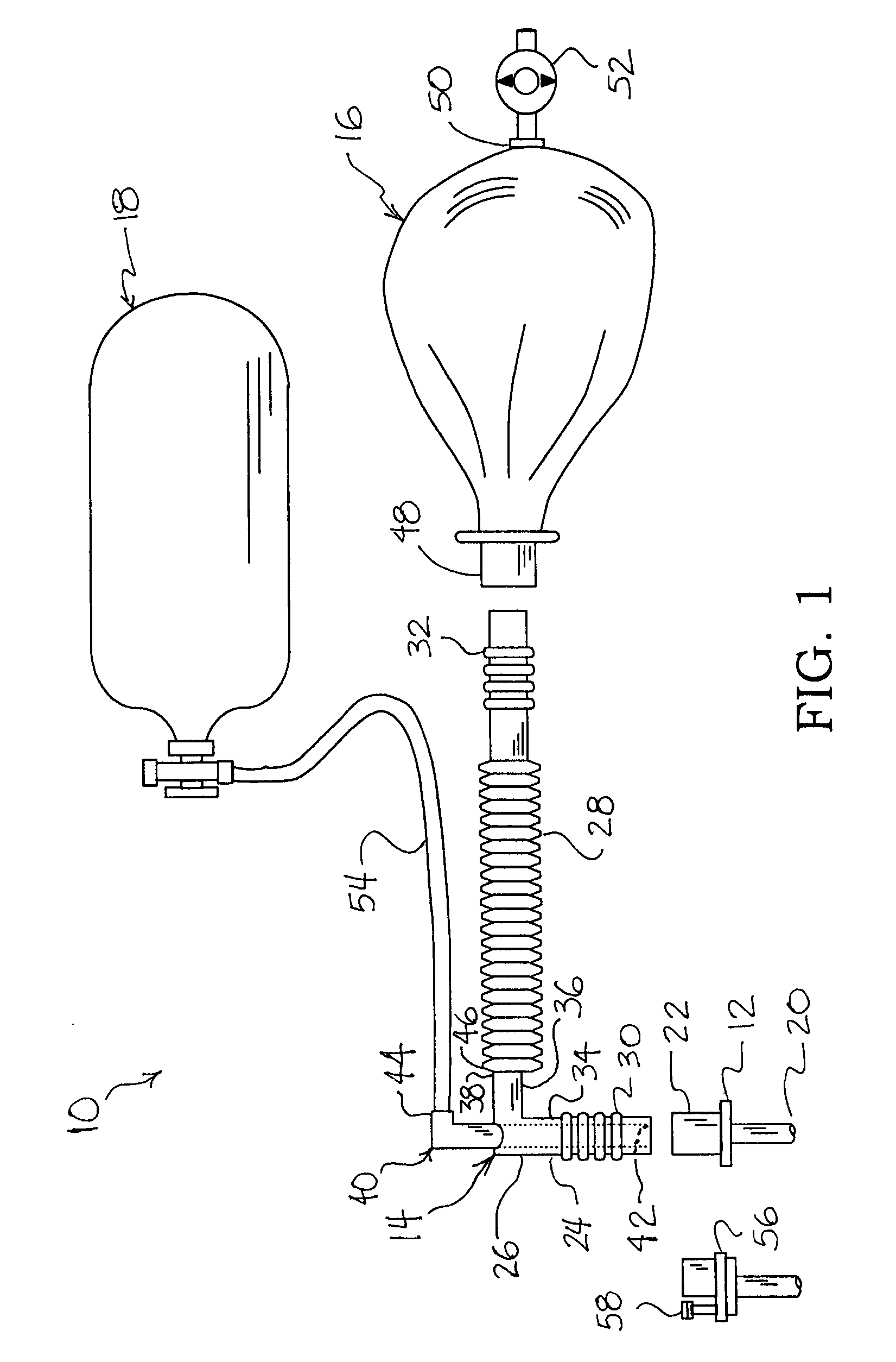
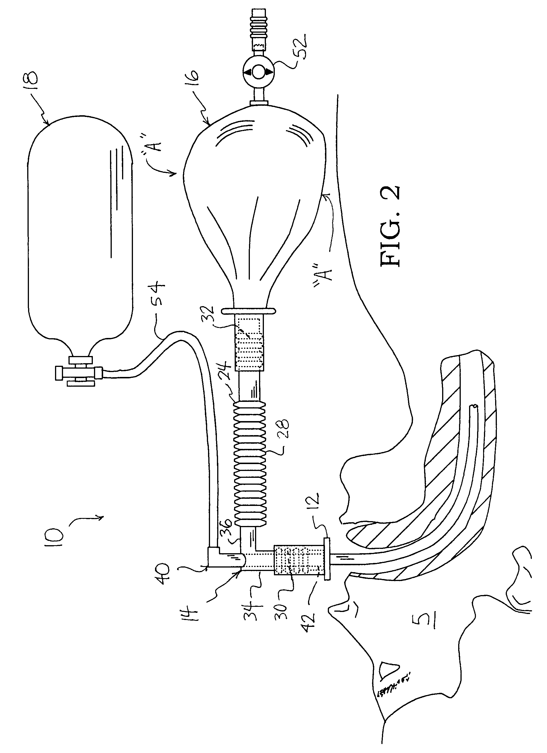
[0024]Referring to the drawings and initially to FIG. 1, breathing circuit 10 includes a patent airway maintaining device 12, a first tube 14 and an inflatable gas bag 16. An external source of oxygen 18 is coupled to tube 14. Breathing circuit 10 combines airway maintaining device 12 with a novel method and structural arrangement of breathing circuit components to supply oxygen at a low pressure to patients.

[0025]Patent airway maintaining device 12 is a conventional device for intubation such as, for example, an endo-tracheal tube or a laryngeal mask airway. Airway maintaining device 12 includes a distal end portion 20 and a proximal end portion 22 and has a tubular wall that defines a fluid tight conduit. Distal end portion 20 can have a range of sizes suitable for humans from infants to adults. Proximal end portion 22 has a standard connector for interfacing with first tube 14. The tubular wall of airway maintaining device 12 defines a first central longitudinal axis.

[0026]Tube 1...


PUM


Abstract

A breathing circuit is described for the supplying of low pressure oxygen to a patient that is at risk of hypoxia. The breathing circuit includes a patent airway maintaining device, a first tube that includes a substantially rigid elbow and connectors and a flexible tubular extension. An inflatable bag is coupled to the first tube and has a pressure relief valve that exhausts into the atmosphere. A second tube has a first end that terminates in proximity to the patent airway maintaining device and a second opposed end that terminates external to the first tube. A third tube connects an external source of oxygen to the second tube. A method for an oxygen breathing circuit is also described that further includes the use of a carbon dioxide monitor and the inflatable bag for assisted breathing. The breathing circuit uses only non-metallic polymer or composite type materials.

Description

BACKGROUND OF THE INVENTION[0001]1. Field of the Invention[0002]The present invention relates to breathing circuits and more specifically to medical applications of low pressure oxygen breathing circuits.[0003]2. Description of the Related Art[0004]An increasing number of surgical procedures are being performed in doctor's offices. This in turn creates many challenges that have to be faced every day in the field of anesthesia. Anesthesia machines are one major type of anesthesia care and include assisted and / or artificial ventilation systems that provide an artificial atmosphere to a patient. These machines supply patients with fresh gases for breathing and remove expiratory waste gases. Fresh gases include inhalation anesthesia agents in combination with other gases, such as oxygen. Anesthesia is typically supplied continuously at flow rates between four and eight liters per minute.[0005]The conduits that supply and remove the artificial atmosphere are commonly referred to as breat...

Claims


Application Information

Patent Timeline
08 Mar 2011
Publication
US7900633B2
IPC
A61M11/00
CPC
A61M16/0045; A61M16/0078; A61M16/0875; A61M16/10; A61M16/085; A61M16/1065; A61M16/107; A61M16/122
Inventors
SINHA, SHAILENDRA K.