Labeling machine

a labeling machine and label technology, applied in the field of labeling machines, can solve the problems of unfavorable labeling, unfavorable labeling, and unfavorable labeling, and achieve the effect of ensuring the structural integrity of the label, engaging easily and conveniently

Active Publication Date: 2011-03-08
OPEN DATA SRL
View PDF43 Cites 0 Cited by
  • Summary
  • Abstract
  • Description
  • Claims
  • Application Information

AI Technical Summary

Benefits of technology

[0017]It is another aspect of the present invention to make available a labeling machine that is provided with a self-regulating braking system, i.e. able to manage the pressure of the tape against the corresponding abutting surface according to the advance or arrest of the tape.
[0018]A further aspect of the present invention is to provide a labeling machine whose replacement of the components of the printing device is easy and simple to perform.
[0019]Additionally, an aspect of the invention is to assure the structural integrity of the labels and of the label holder tape, while assuring the quality of the print effected by the printing device.
[0024]According to another aspect of the present invention, there is provided a labeling machine wherein: the arresting device further comprises an auxiliary elastic member, operatively interposed between an abutting portion of the first element and an abutting surface of the second element oriented opposite to the contrasting surface, the auxiliary elastic member co-operating with the at least one elastic member to enhance the thrusting action of the second element against the contrasting surface when the arresting device is in arresting condition.

Problems solved by technology

While known labeling machines allow the printing and the satisfactory application of the labels on the packages and / or surfaces of the products of interest, the Applicant has noted that they are not free of serious and detrimental drawbacks, mainly, in relation to the operation and the wear of the arresting device, to the replacement and / or maintenance of one or more components of the printing device, as well as to the wear of the labels and / or of the label holder tape.
In particular, the related art has failed to appreciate that that the constant and continuous pressure of the arresting device on the label holder tape against the respective abutting surface, determines, in the long run, significant problems with the calibration of the components of said device, as well as excessive wear of the mechanical parts in rubbing or rolling relationship, requiring constant interventions to maintain and / or replace one or more components of the arresting device.
This serious detriment also has an impact on the general conditions of the label holder tape and on the labels themselves, which may be structurally compromised, presenting an aesthetically displeasing outside appearance and / or, worse yet, an irregular printing surface whereon the ink used is deposited imprecisely, giving rise to undesired imperfections.
It should also be noted that both the difficulty in accessing the internal areas of the load-bearing structure of known labeling machines, and the difficulty in replacing some components of the printing device, e.g. the inking roller and the like, normally provided, entails and intense maintenance activity, whilst requiring considerable manual skills of the maintenance operator who must, with particular instruments and tools, access the inking roller to extract it from the structure and replace it with another inking roller.

Method used


Image

  • Labeling machine
  • Labeling machine
  • Labeling machine

Examples


Embodiment Construction

[0057]Reference will now be made in detail to several embodiments of the invention that are illustrated in the accompanying drawings. Wherever possible, same or similar reference numerals are used in the drawings and the description to refer to the same or like parts or steps. The drawings are in simplified form and are not to precise scale. For purposes of convenience and clarity only, directional terms, such as top, bottom, up, down, over, above, and below may be used with respect to the drawings. These and similar directional terms should not be construed to limit the scope of the invention in any manner. The words “connect,”“couple,” and similar terms with their inflectional morphemes do not necessarily denote direct and immediate connections, but also include connections through mediate elements or devices.

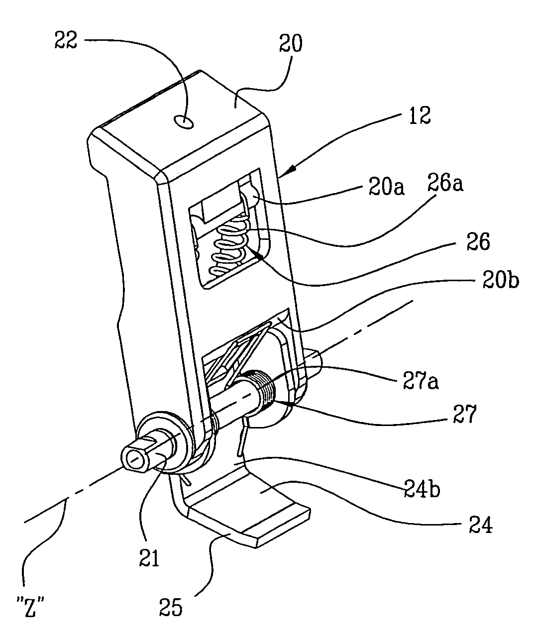
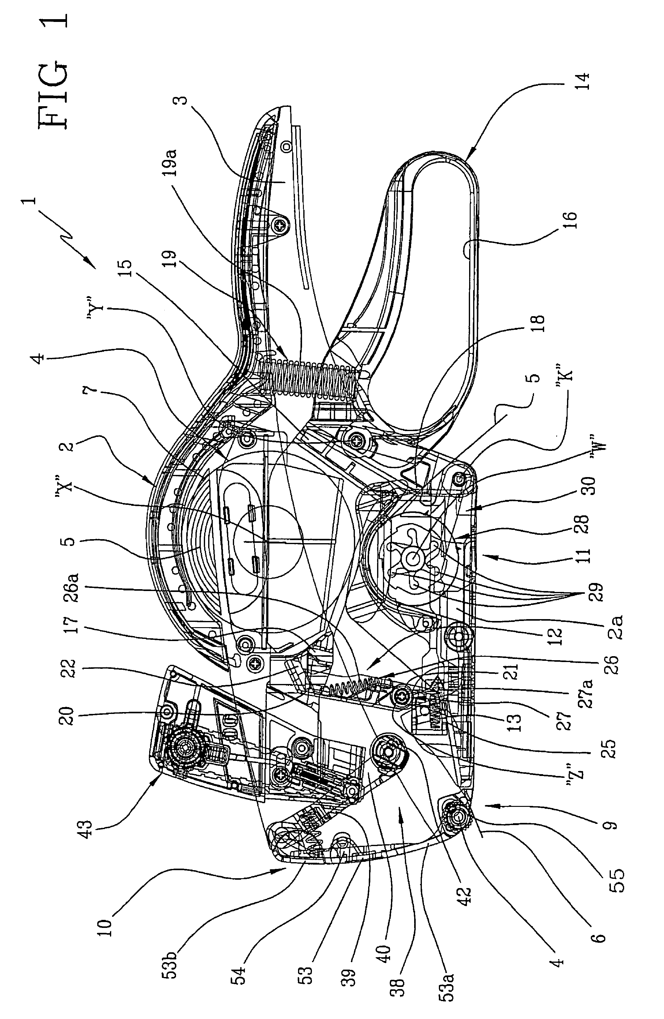
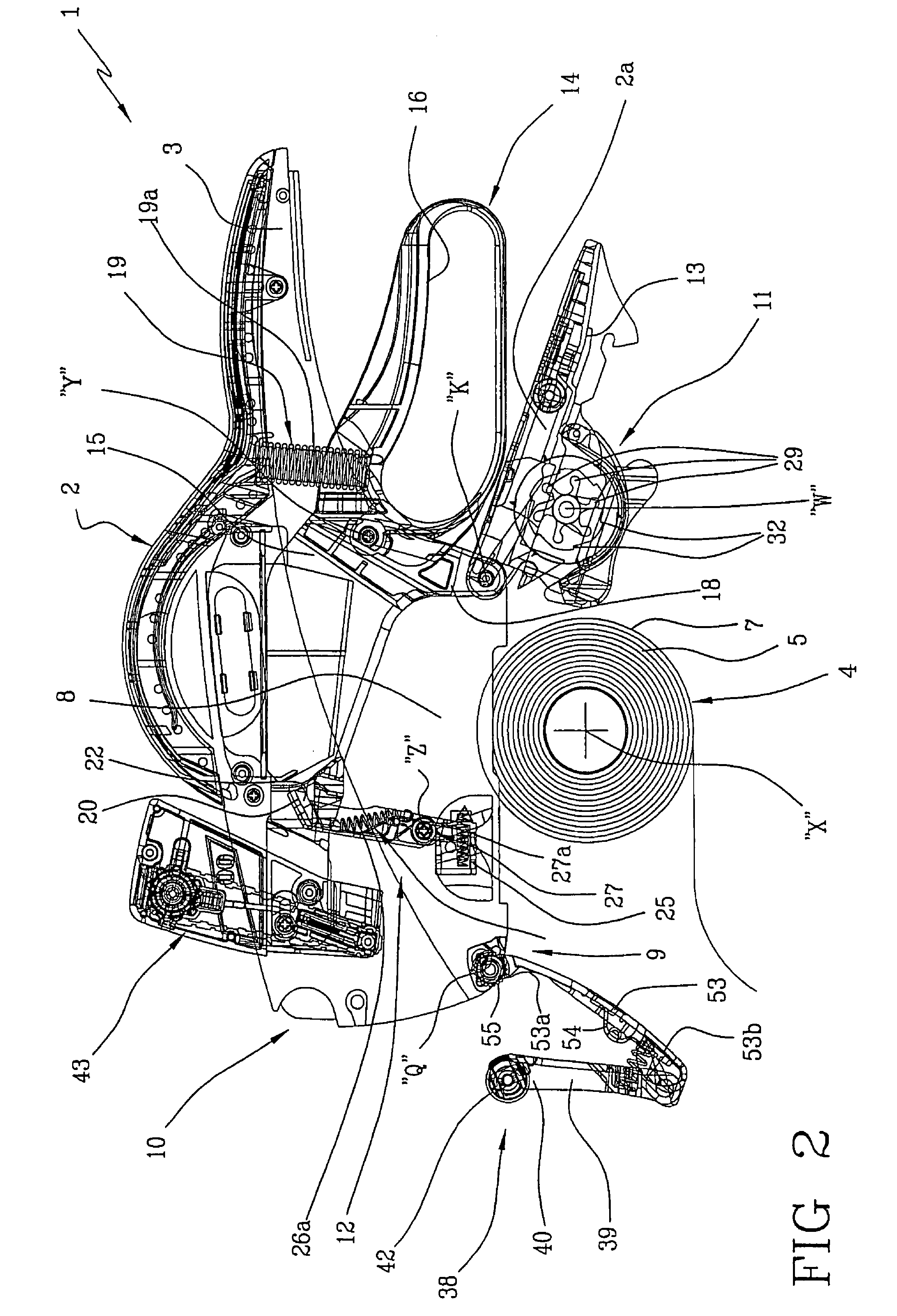
[0058]With reference to the accompanying figures, the number 1 globally indicates a labeling machine, in accordance with the present invention.

[0059]As shown in FIGS. 1 and 2...


PUM

PropertyMeasurementUnit
pressureaaaaaaaaaa
angleaaaaaaaaaa
rotationaaaaaaaaaa

Abstract

A labeling machine comprises a self-regulating arresting member of a label holder tape. The arresting member is able to press the tape against an abutting surface when a label has to be applied on a destination surface and it releases said tape when, on the action of a control device the tape is actuated to advance. The labeling machine further comprises a printing device whose inking roller is associated to a device that enables it to be engaged easily and conveniently on a respective support arm. The support arm in turn is advantageously connected to an access door to internal areas of the labeling machine, whose opening determines the exit of the support arm and the exposure of the inking roller.

Description

CROSS REFERENCE TO RELATED APPLICATIONS[0001]This application references and claims priority from Italian Application Ser. No. RM2007A000258 filed May 8, 2007. This application additionally claims priority from U.S. Design Pat. App. Ser. No. 29 / 297,000 filed Nov. 1, 2007 now U.S. Pat. No. Des. 607,491 which in-turn claims priority from Italian Design Ser. No. RM20070000065 filed May 8, 2007. The entire contents of each application are herein incorporated fully by reference.FIGURE SELECTED FOR PUBLICATION[0002]FIG. 1BACKGROUND OF THE INVENTION[0003]1. Field of the Invention[0004]The present invention relates to a labeling machine. In particular, the present invention relates to a labeling machine with manual operation for applying labels bearing one or more captions, e.g. indications about the products whereon said labels are applied or the prices of the products. In further detail, the present invention is suitable for use in warehouses and / or in any commercial activity, such as dep...

Claims


Application Information

Patent Timeline
Patent Type & Authority Patents(United States)
IPC IPC(8): B65C11/02B65C9/46B32B37/00B29C65/48
CPCB65C11/0236B65C2210/0081Y10T156/1795Y10T156/17Y10T156/18
Inventor ARENA, GIORGIO
Owner OPEN DATA SRL
Why Eureka
Try Eureka