
Container

a container and fluid technology, applied in the field of containers, can solve the problems of reducing affecting the overall structure of the container, and the zipper of the bag is more likely to burst, so as to reduce the pressure on the container

Inactive Publication Date: 2011-03-08
CHEN KERN JEN
View PDF8 Cites 20 Cited by
  • Summary
  • Abstract
  • Description
  • Claims
  • Application Information

AI Technical Summary

Benefits of technology

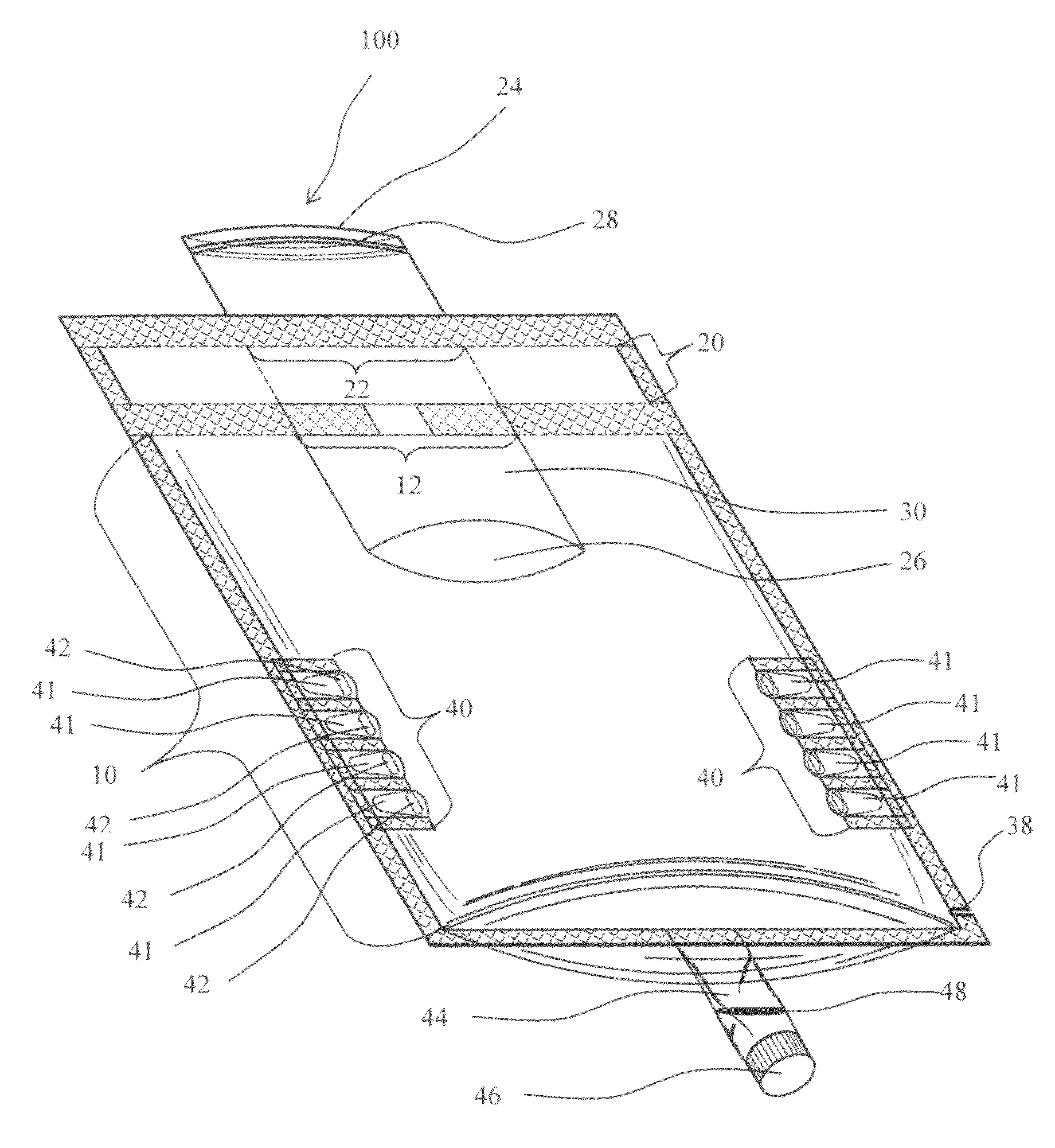
[0005]In view of the drawbacks of conventional containers, an object of the present invention is to provide a highly crashworthy container. A container of the present invention comprises a pressure buffer area that can reduce the impact force exerted upon the container. This design prevents the container from being broken easily and the fluid from spilling over accordingly.
[0013]In a preferred embodiment, a side edge of the cavity is further provided with an easy-tearing notch.
[0020]A container of the present invention comprises a pressure buffer area; therefore, when the container is pressed by an external force, the fluid or gas inside the container can flow to the pressure buffer area through the directing hole, thereby reducing the pressure exerted upon the container. Consequently, the container cannot be broken easily. A container of the present invention is applicable in many situations and is thus useful for containing all kinds of fluids.

Problems solved by technology

A zip lock bag uses a zipper to seal and lacks other specific designs to enhance its overall structure.
Therefore, when a shock force exerts upon a zip lock bag containing a fluid, the zipper of the bag is more likely to burst.
As for an aseptic pack, though a more crashworthy container compared to a zip lock bag, it cannot be reopened and reused like a zip lock bag.
A PET bottle overcomes the above drawbacks of the other two types of containers; however, a PET bottle has a more rigid structure, making it inconvenient to store or carry and affecting its usefulness.

Method used


Image

  • Container
  • Container
  • Container

Examples


Embodiment Construction

[0029]Advantages and features of the present invention will be described more fully hereinafter with reference to the accompanying drawings, in which preferred embodiments of the invention are shown. This invention may, however, be embodied in many different forms and should not be construed as limited to the embodiments set forth herein. Various changes and modifications can be made by those skilled in the art without departing from the spirit and scope of this invention. It is intended that the scope of the invention be defined by the claims appended hereto.

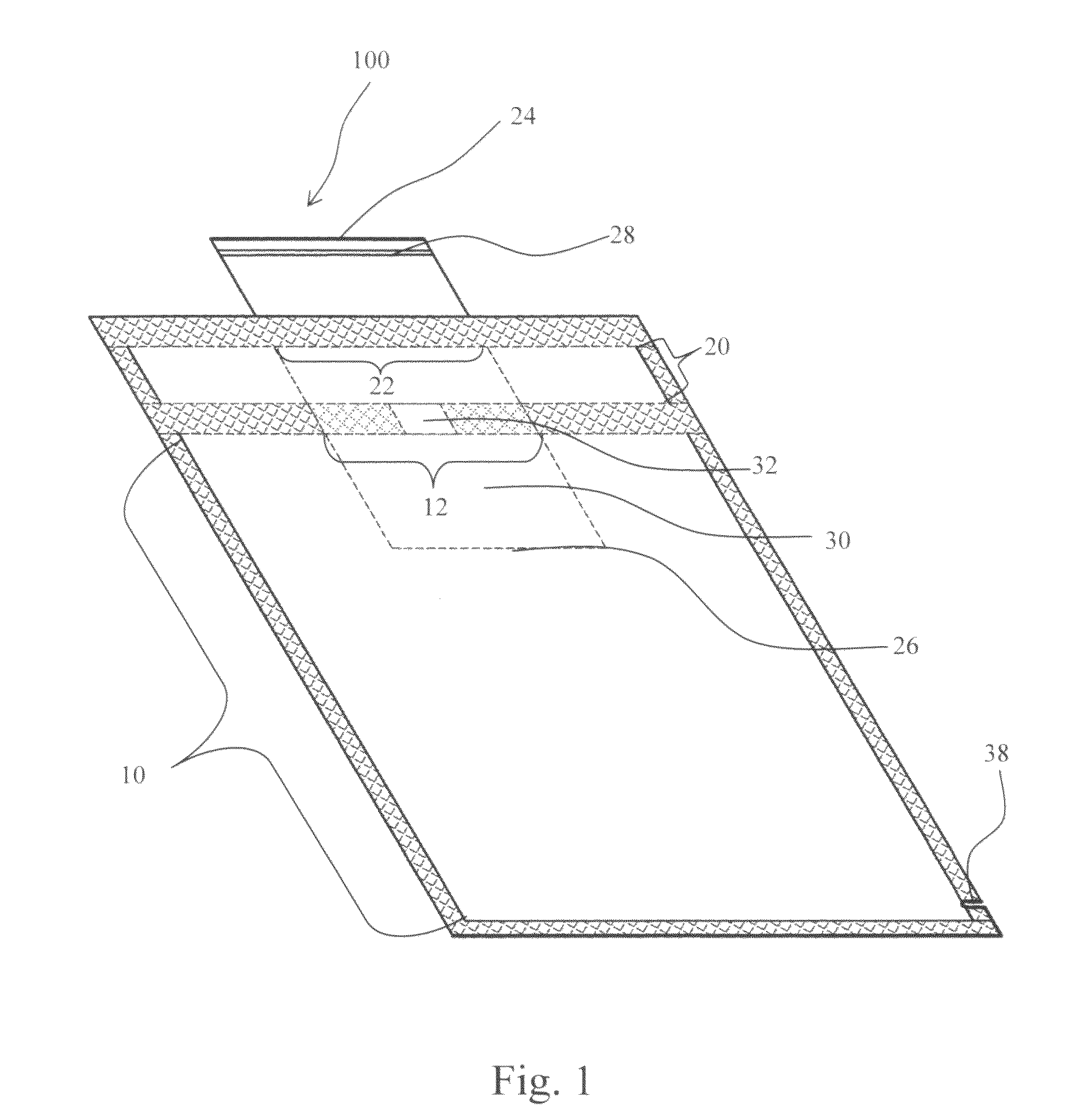
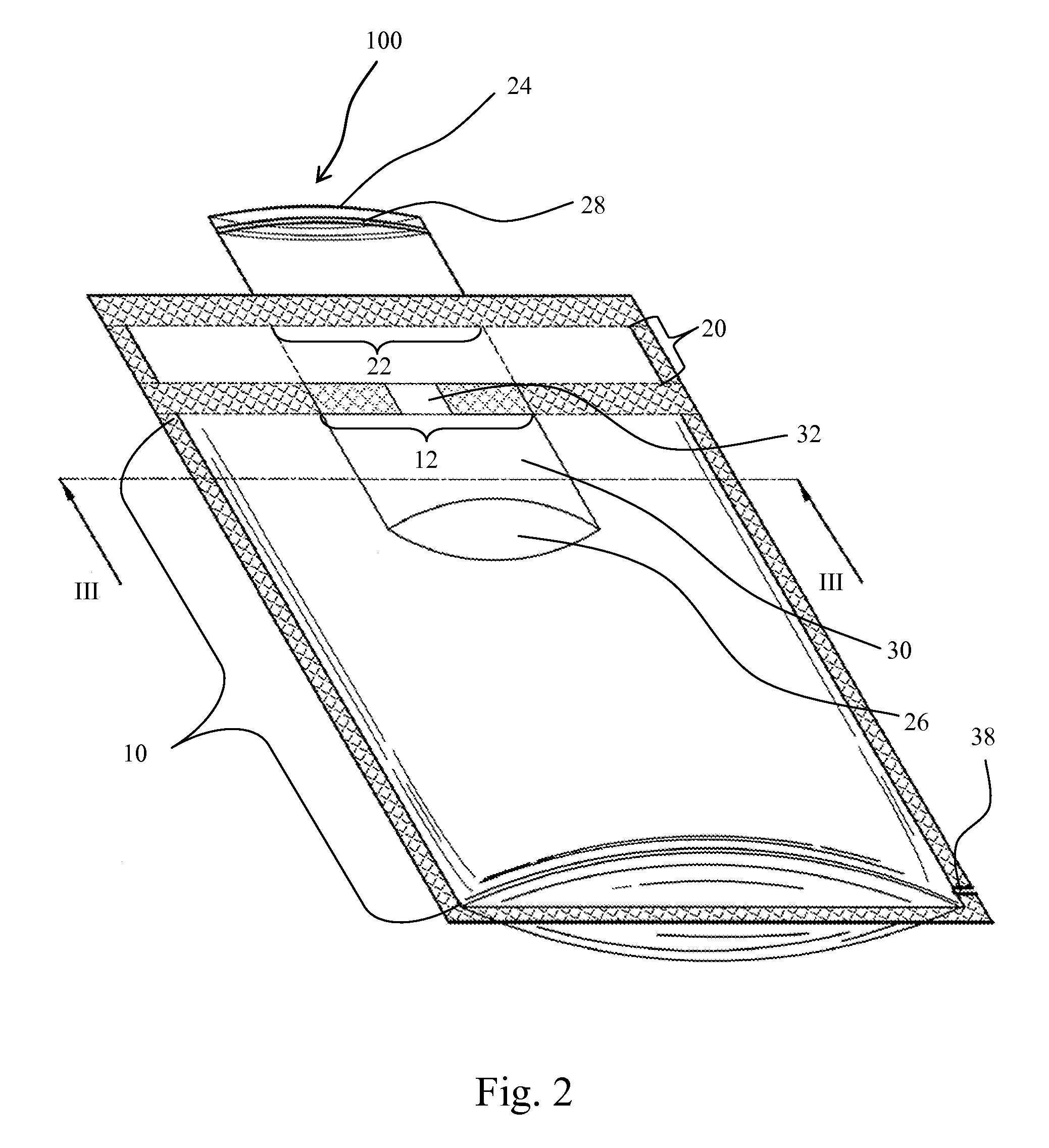
[0030]For the purpose of better illustration, the embodiments hereinafter only describe containers with fluids contained therein. A skilled person in the art would know that a container of the present invention may contain substances other than fluids. FIG. 1 is a schematic view showing a container according to the present invention when it is flat with no fluids contained therein. As shown in FIG. 1, a fluid container 100 of t...


PUM


Abstract

The present invention provides a container, comprising: a cavity provided with a first opening portion; a pressure buffer area which is positioned above the cavity and the first opening portion and which is provided with a second opening portion corresponding to the first opening portion; and a thin film channel which extends through the first opening portion and the second opening portion and which has an inner channel wall and an outer channel wall, wherein the inner channel wall forms a passage for fluids with an inlet end and an outlet end, the inlet end being positioned outside the second opening portion of the pressure buffer area with a first opening and closing structure and the outlet end being positioned inside the cavity, and wherein the second opening portion is hermetically connected to the outer channel wall while the first opening portion is hermetically connected to the outer channel wall except for the area of at least one directing hole formed therebetween, such that a fluid under pressure flows back to the pressure buffer area through the directing hole.

Description

BACKGROUND OF THE INVENTION[0001]1. Field of the Invention[0002]The present invention relates to a container, and more particularly, to a crashworthy fluid container.[0003]2. Description of the Related Art[0004]Fluid containers that are most commonly used by consumers nowadays may include zip lock bags, aseptic packs, and polyethylene terephthalate (PET) bottles; however, these types of containers all have certain drawbacks. A zip lock bag uses a zipper to seal and lacks other specific designs to enhance its overall structure. Therefore, when a shock force exerts upon a zip lock bag containing a fluid, the zipper of the bag is more likely to burst. As for an aseptic pack, though a more crashworthy container compared to a zip lock bag, it cannot be reopened and reused like a zip lock bag. A PET bottle overcomes the above drawbacks of the other two types of containers; however, a PET bottle has a more rigid structure, making it inconvenient to store or carry and affecting its usefulne...

Claims


Application Information

Patent Timeline
IPC IPC(8): B65D25/08
CPCB65D81/3272
Inventor CHEN, KERN-JEN
Owner CHEN KERN JEN
Learn More