
Metal gasket

a technology of metal gaskets and metal plates, applied in the direction of engine seals, metal-working devices, sealing arrangements, etc., can solve the problems of improper positioning the small positioning holes of the third metal plate positioning holes with respect to the wrong direction, so as to prevent the assembly of errors

Inactive Publication Date: 2011-03-08
ISHIKAWA GASKET CO LTD
View PDF7 Cites 9 Cited by
  • Summary
  • Abstract
  • Description
  • Claims
  • Application Information

AI Technical Summary

Benefits of technology

"The present invention provides a metal gasket which is formed by laminating three or more metal plates and held between two members for sealing a sealing hole. The metal plates have multiple positioning holes that are shaped in such a way that at least one positioning hole does not have the other positioning hole in shape when they overlap with respect to a predetermined direction determined by the planar shape of the metal gasket. The positioning holes of the first metal plate are shaped in such way that one positioning hole does not match the other positioning hole, and positioning projections fitted into the facing positioning holes of the first metal plate are formed in such way that the upper side is smaller than the lower side. The small positioning holes of the third metal plate are made differently, and positioning projections are formed in such way that they do not fit the wrong positioning holes. This design prevents positioning holes from being mistaken and ensures proper fitting of the metal plates. The metal gasket can be easily laminated properly, and if the lamination direction is wrong, the wrong lamination can be easily recognized. The invention prevents erroneous assembly and ensures accurate and reliable sealing."

Problems solved by technology

Also, in the metal gasket, the positioning holes of the first metal plate are shaped in such a way that one positioning hole does not match the other positioning hole, so that when the first metal plate is placed over the second metal plate, the position holes do not properly enter the positioning projection with respect to the wrong direction.
When the third metal plate is placed over the first metal plate, the small positioning holes of the third metal plate do not properly enter the positioning projections with respect to the wrong direction.

Method used


Image

  • Metal gasket
  • Metal gasket
  • Metal gasket

Examples


Embodiment Construction

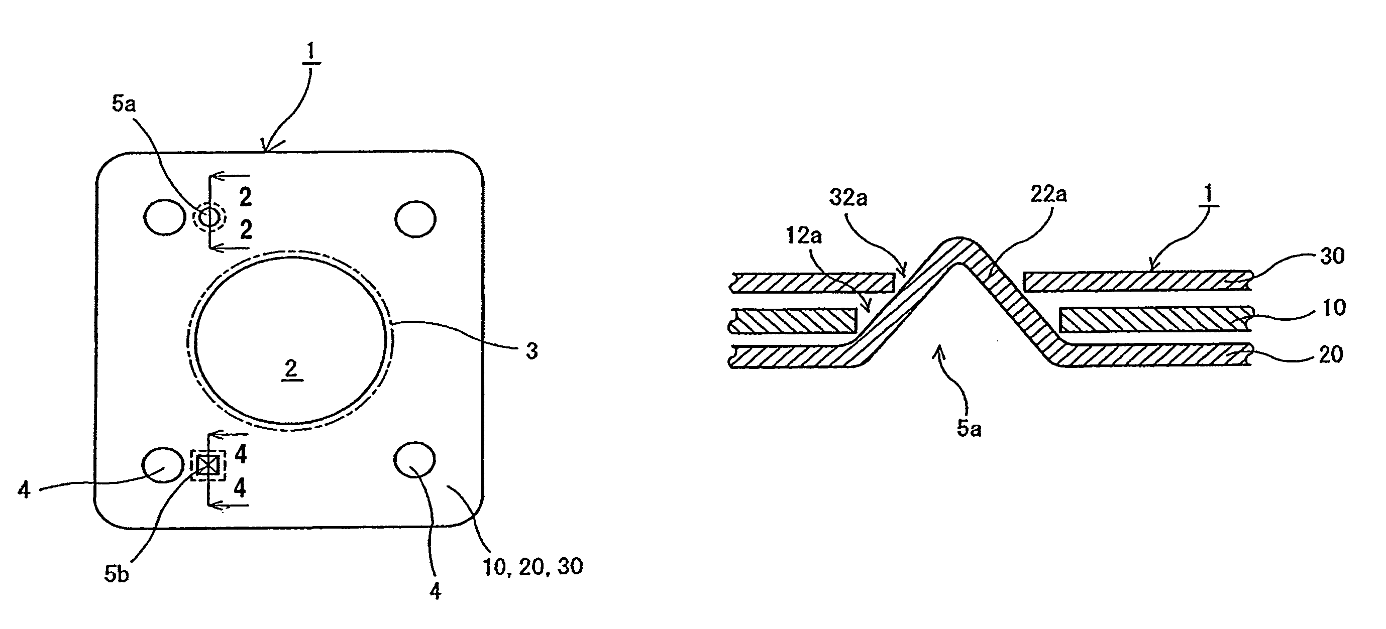
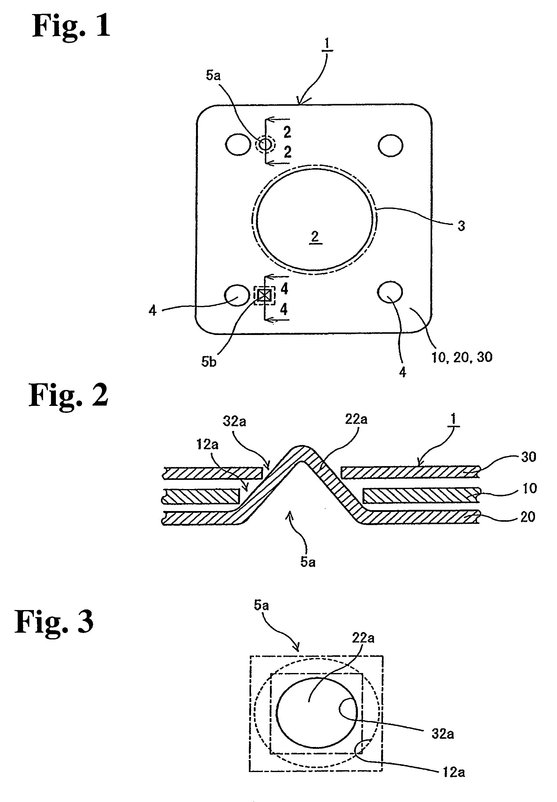
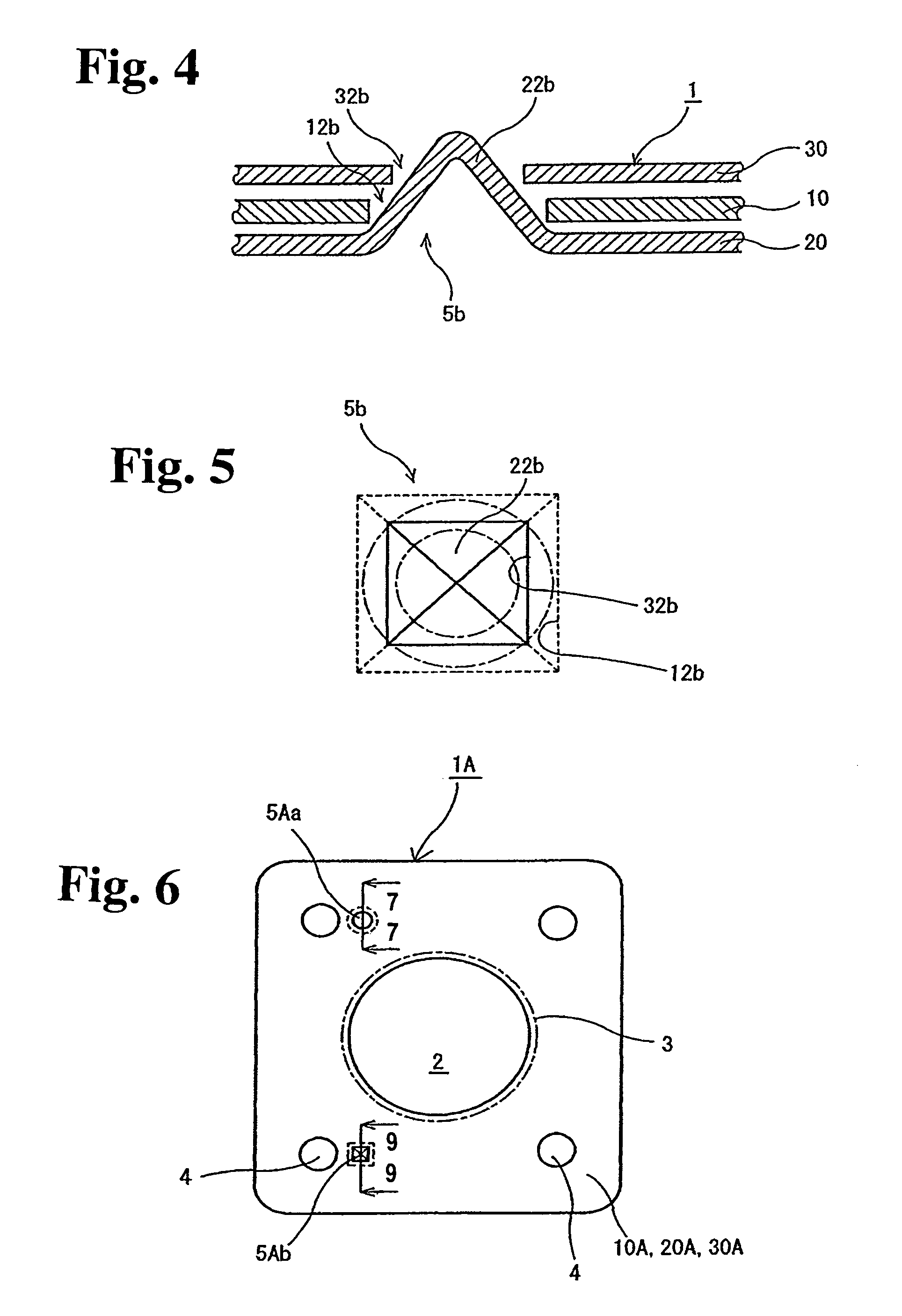
[0036]Hereunder, embodiments of a metal gasket and a method of manufacturing the same according to the present invention will be described with reference to the attached drawings as examples of the metal gasket held between an exhaust manifold for an engine and a flange for an exhaust pipe. However, this invention is not limited to the embodiment and can be applied to, for example, other metal gaskets such as a gasket for an intake manifold, cylinder head gasket and so on. Incidentally, FIGS. 1-20 are schematic explanatory views in which thicknesses of plates, and sizes of sealing-target holes, beads, positioning holes, positioning projections and so on are different from actual ones and enlarged for the sake of explanation.

[0037]First, the metal gasket of the first embodiment of the invention will be explained. As shown in FIGS. 1-5, the metal gasket 1 of the first embodiment includes three metal structural plates 10, 20, 30 manufactured by matching to the shape of the flange of th...


PUM

PropertyMeasurementUnit
sizeaaaaaaaaaa
shapesaaaaaaaaaa
sizesaaaaaaaaaa

Abstract

A metal gasket includes a first metal plate having positioning holes, and a second metal plate laminated under the first metal plate. The second metal plate has positioning projections facing corresponding positioning holes and fitted into the facing corresponding positioning holes. At least one of the positioning holes does not match the other of the positioning holes in case the position holes are overlapped, and at least one of the positioning projections is not fitted into the other of the positioning holes.

Description

BACKGROUND OF THE INVENTION AND RELATED ART STATEMENT[0001]The present invention relates to a metal gasket which is formed by laminating metal plates and held between two members for sealing. More specifically, the invention relates a metal gasket which can prevent erroneous assembly.[0002]For an automobile engine, metal gaskets such as a gasket sealing a simple sealing-target hole at an intake manifold or exhaust manifold and so on; or a cylinder head gasket sealing between a cylinder head and a cylinder block, are used. The above-mentioned metal gaskets are manufactured by laminating multiple metal plates with different materials, thicknesses, or processes, and in order to obtain a desired sealing capability, these multiple metal plates are required to be laminated in a correct direction on a correct side in a correct order.[0003]However, in many cases, the shapes of the metal plates have roughly the same configuration, so that it is difficult to determine the directions, front or...

Claims


Application Information

Patent Timeline
Patent Type & Authority Patents(United States)
IPC IPC(8): F02F11/00F16J15/02
CPCF16J15/0831F02F11/002F02F7/0082Y10T29/49297F16J15/08
Inventor IMAI, TOSHIHIRO
Owner ISHIKAWA GASKET CO LTD
Learn More