Supercharge Your Innovation With Domain-Expert AI Agents!

Storage device with disk power control based on logical storage area

a storage device and power control technology, applied in the field of storage devices, can solve the problems of inability to respond immediately to access by the host computer, affecting the overall performance of the storage device, and not being able to perform processing to shift the magnetic disk device to a variety of power saving modes

Inactive Publication Date: 2011-03-08
HITACHI LTD
View PDF9 Cites 10 Cited by
  • Summary
  • Abstract
  • Description
  • Claims
  • Application Information

AI Technical Summary

Benefits of technology

The present invention provides a storage device that allows power saving control for magnetic disk devices to be appropriately set by a management device of the storage device. The storage device is often shared by multiple applications or administrators, which may lead to inconsistencies with the power saving control of the magnetic disk devices. To address this issue, the present invention provides a method that ensures consistency between instructions from administrators and the operating states of the magnetic disk devices in the storage device. Even if there is no consistency, the method allows the storage device to monitor the usage states of the other magnetic disk devices until consistency is ensured and then execute power saving control at the point where the operation with respect to the magnetic disk device by application B has not been performed for a fixed period. This ensures efficient power saving control and reduces the risk of inconsistencies between applications.

Problems solved by technology

However, when a magnetic disk device temporarily stops rotating, same is unable to immediately respond to access by the host computer.
Usage of the above control method that is generally employed for magnetic disk devices means that it takes time for the magnetic disk devices to operate in the event of an access request and the overall performance of the storage device drops considerably.
However, with the technology that appears in Japanese Application Laid Open No. 2000-293314, unless a number of hours have elapsed since the storage device is accessed, the processing to shift the magnetic disk device to a variety of power saving modes is not executed.
That is, excess power is consumed by a magnetic disk device which is known to have not been accessed by an application for several hours.

Method used


Image

  • Storage device with disk power control based on logical storage area
  • Storage device with disk power control based on logical storage area
  • Storage device with disk power control based on logical storage area

Examples


Embodiment Construction

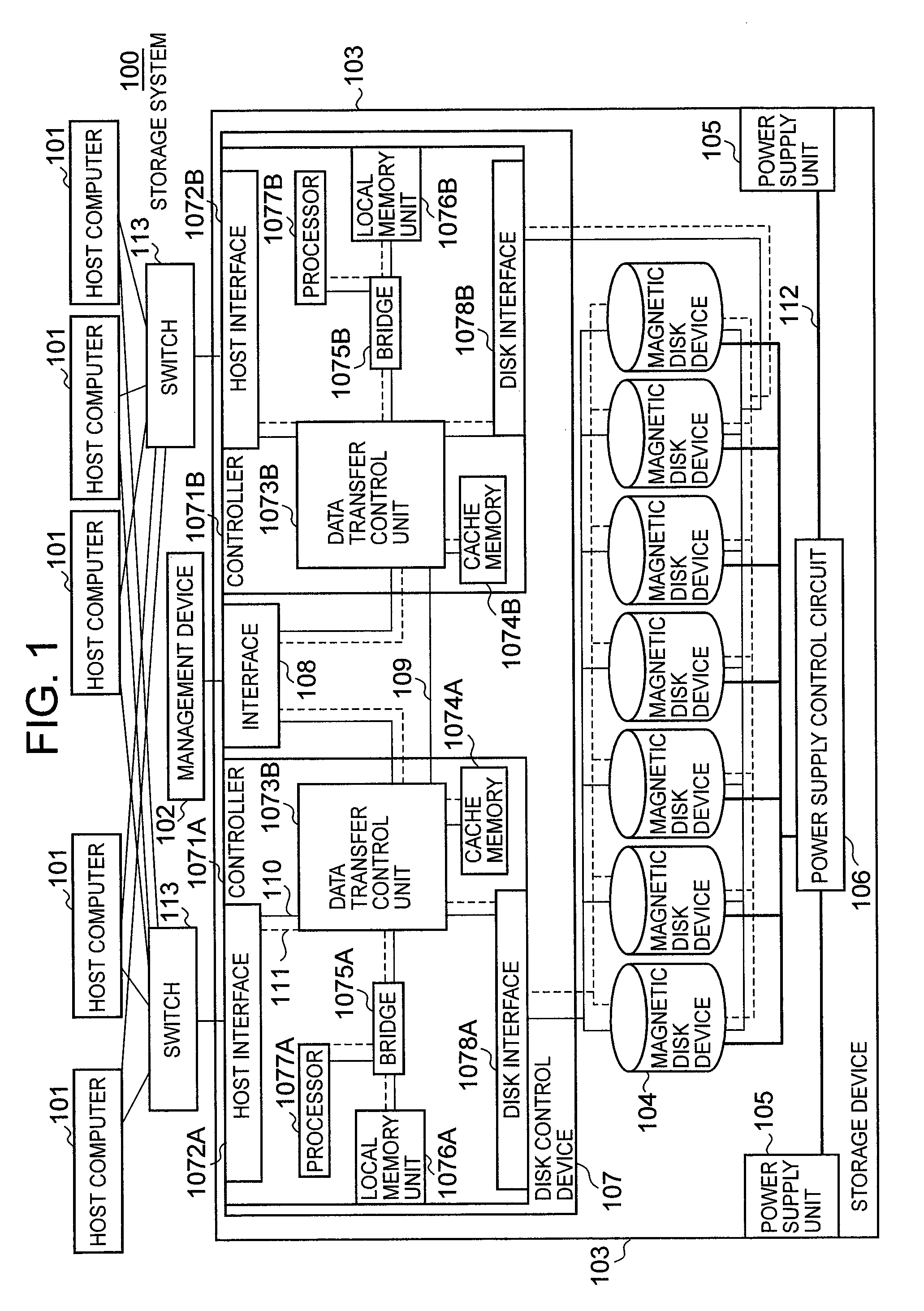
An embodiment of the present invention will be described hereinbelow with reference to the drawings. FIG. 1 is a configuration view of a storage system 100 according to this embodiment.

The storage system 100 comprises a host computer 101, a management device 102, and a storage device 103. The storage device 103 comprises a plurality of magnetic disk devices 104, a power supply unit 105 which supplies power to the magnetic disk devices 104, a power supply control circuit 106 which performs power supply switching, and a disk control device 107. The host computer 101 and management device 102 are connected to the plurality of magnetic disk devices 104 via the disk control device 107.

The host computer 101 is a computer that comprises information processing resources such as a CPU (Central Processing Unit) and memory, for example, and is specifically constituted by a personal computer, a workstation, or a mainframe or the like. The host computer 101 sets logical storage areas (‘LU’ herei...


PUM


Abstract

The present invention makes is possible to appropriately set the power saving control of the storage device from the management device of the storage device. In addition, the storage device executes control of the power saving for the magnetic disk device after ensuring consistency between an instruction from the administrator and the operating state of the magnetic disk device in the storage device.

Description

CROSS-REFERENCE TO PRIOR APPLICATIONThis application relates to and claims the benefit of priority from Japanese Patent Application number 2007-48331, filed on Feb. 28, 2007, and Japanese Patent Application number 2007-261511, filed on Oct. 5, 2007 the entire disclosure of which are incorporated herein by reference.BACKGROUNDThe present invention generally relates to a storage device.The method generally used to control a magnetic disk device involves turning the power ON when access is received, executing rotation of the magnetic storage medium, responding to access by a host computer, and, after access is complete, turning OFF the power of the motor used to rotate the magnetic storage medium in a stepwise fashion. That is, magnetic disk devices contain various power saving modes and mainly possess a function to select a predetermined power saving mode when access is being received and to automatically shift to this mode.A storage device comprises a storage unit in which a pluralit...

Claims


Application Information

Patent Timeline
Patent Type & Authority Patents(United States)
IPC IPC(8): G06F12/00
CPCG11B17/228G11B33/128
Inventor MURAMATSU, KOTAROYAGISAWA, IKUYAZIMOTO, YOSHIFUMI
Owner HITACHI LTD
Features
  • R&D
  • Intellectual Property
  • Life Sciences
  • Materials
  • Tech Scout
  • Unparalleled Data Quality
  • Higher Quality Content
  • 60% Fewer Hallucinations
Learn More