Flow vortex suppression apparatus for a mass air flow sensor

a sensor and flow vortex technology, applied in auxillary pretreatment, instruments, separation processes, etc., can solve the problems of reducing the signal quality affecting the calibration of the mass air flow sensor in undesired ways, and reducing the reliability of the mass air flow sensor. , to achieve the effect of reducing the variation and noise of the flow signal, reducing the turbulence and diffuse vortex, and reducing the turbulen

Active Publication Date: 2011-03-15
MANN HUMMEL GMBH
View PDF19 Cites 14 Cited by
  • Summary
  • Abstract
  • Description
  • Claims
  • Application Information

AI Technical Summary

Benefits of technology

[0015]In another aspect of the invention the fibrous vortex dispersive media is operable to entrap at least a portion of particulate contaminants present in the air flow in the air intake tract thereby further protecting the mass air flow sensor.
[0016]In another aspect of the invention the vortex suppression apparatus is additionally operable to dampen noise levels transmitted through the air intake duct, reducing apparent engine noise.
[0018]In another aspect of the invention a flow vortex suppression apparatus is provided for the engine air intake mass air flow sensor housing. The air flow permeable fibrous vortex dispersive media is provided at an air inlet side of the housing. The flow vortex suppression apparatus is configured to constrain the air flow in the mass air flow sensor housing to pass through the fibrous vortex dispersive media before reaching the air flow sensor such that the vortex dispersive media is configured to diffuse vortices and reduce air flow turbulence entering the mass flow sensor and reduce variations and noise in a flow signal from the sensor.

Problems solved by technology

This mass air flow calibration can be affected in undesired ways by the presence of vortices that may be present in the air flow stream.
The fluid velocities in these vortices can be detected by the mass air flow sensor and contribute to measurement errors in the intake air flow with the result that the mass air flow sensor becomes a less reliable indicator of the quantity of air flow into the engine.
The geometry of the air filter may contribute to the generation of shear layers in the air flow at the outlet side of the air filter, which may result in the generation of vortices in the air stream entering the mass air flow sensor and the resultant reduction in mass air flow sensor signal quality.
While such solutions are serviceable, they are disadvantageous from a total system cost point of view.

Method used


Image

  • Flow vortex suppression apparatus for a mass air flow sensor
  • Flow vortex suppression apparatus for a mass air flow sensor
  • Flow vortex suppression apparatus for a mass air flow sensor

Examples


Embodiment Construction

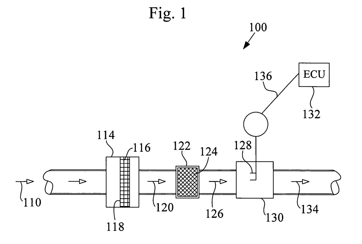
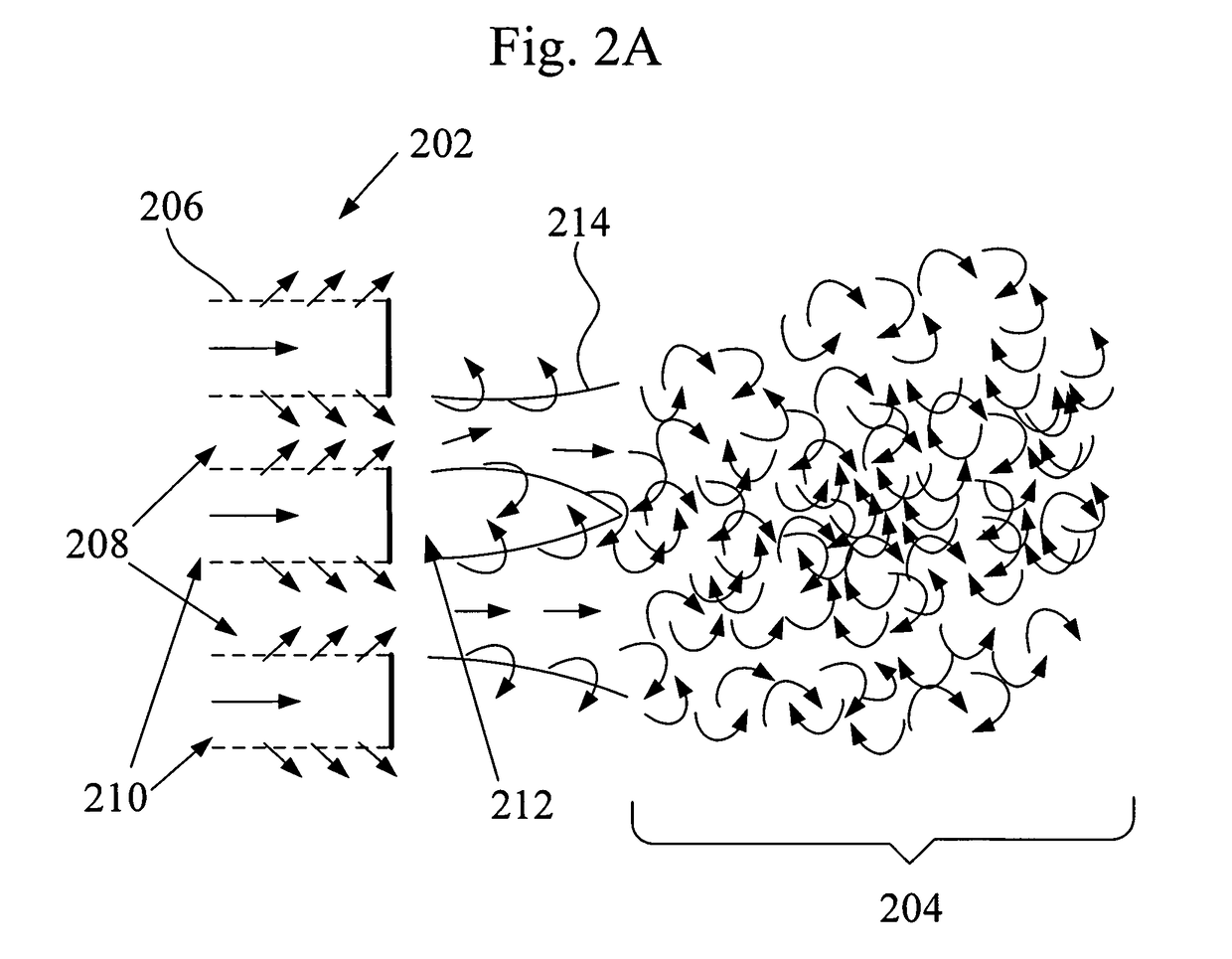
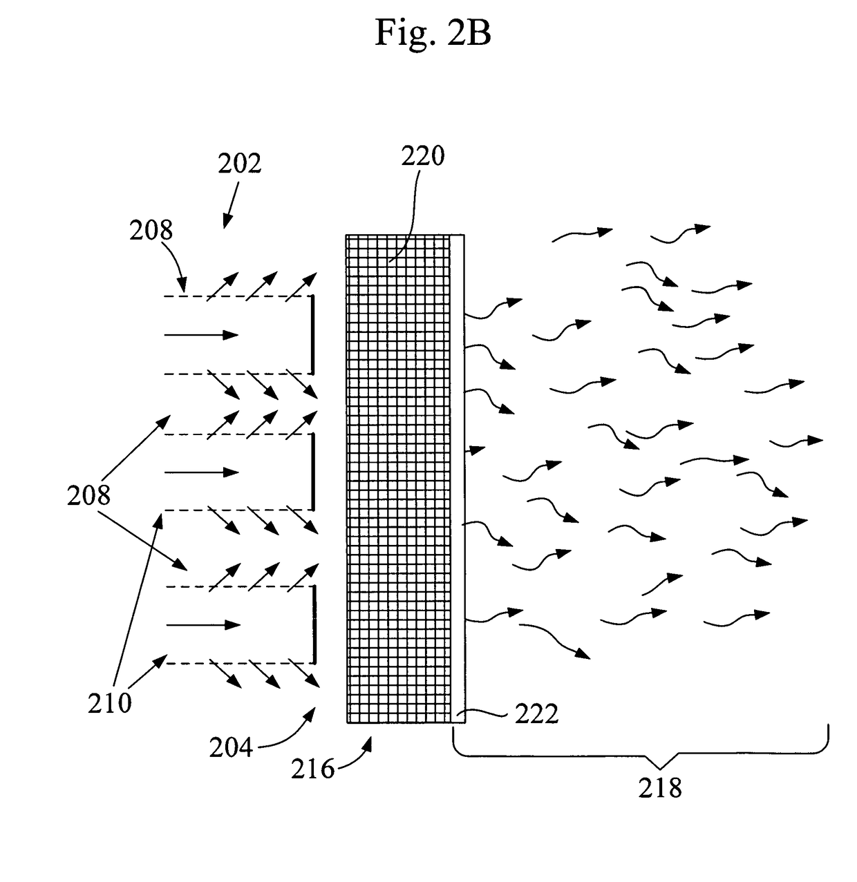
[0034]Before describing in detail embodiments that are in accordance with the present invention, it should be observed that the embodiments reside primarily in combinations of method steps and apparatus components related to an apparatus and method of improving the measurement signal (performance) of a mass air flow sensor by diffusion of vortices and reduction of flow turbulence using the flow vortex suppression apparatus as disclosed herein. Accordingly, the apparatus components and method steps have been represented where appropriate by conventional symbols in the drawings, showing only those specific details that are pertinent to understanding the embodiments of the present invention so as not to obscure the disclosure with details that will be readily apparent to those of ordinary skill in the art having the benefit of the description herein.

[0035]In this document, relational terms such as first and second, top and bottom, and the like may be used solely to distinguish one enti...


PUM

PropertyMeasurementUnit
dimensionsaaaaaaaaaa
noise levelsaaaaaaaaaa
forcesaaaaaaaaaa

Abstract

In various aspects of the invention a flow vortex suppression apparatus for use in an air intake duct having a mass air flow sensor is disclosed. The flow vortex suppression apparatus includes an air flow permeable fibrous vortex dispersive media installed into the air duct in a position upstream of the mass flow sensor and configured to occlude the air duct such that air flow in the duct is constrained to pass through the vortex dispersive media. The vortex dispersive media is configured and adapted to diffuse vortices and reduce air turbulence of an air stream entering the mass flow sensor, thereby reducing variations and noise in a flow measurement signal from the mass air flow sensor.

Description

TECHNICAL FIELD[0001]This disclosure relates to mass air flow measurement in an engine air intake tract and apparatus to improve mass air flow sensor performance by reducing turbulence and vortices in the air flow.BACKGROUND OF THE INVENTION[0002]Mass air flow sensors are typically applied to measure the amount of air entering the air intake tract of an internal combustion engine. So as to reduce pollution and to provide a cleaner and more complete fuel combustion, the mass air flow sensor signal is provided to a specialized computing device (sometimes called an engine control unit or ECU) that utilizes the air flow signal, among other measured signals, to calculate and regulate the proper amount of fuel to deliver to the engine for efficient combustion.[0003]It is known that air density varies with temperature and pressure (often affected by the altitude at which the vehicle engine operates). The mass air flow sensor is applied to measure the mass flow of air in the intake tract to...

Claims


Application Information

Patent Timeline
Patent Type & Authority Patents(United States)
IPC IPC(8): G01F1/32
CPCF02M35/024F02M35/10013F02M35/10262G01F1/6842G01F15/12F02M35/10386Y02T10/146F15D1/02G01F15/00G01F15/125Y02T10/12
Inventor JASNIE, JASRIS
Owner MANN HUMMEL GMBH
Why Eureka
Try Eureka