Bush cutting machine

a cutting machine and bust technology, applied in the field of bust cutting machines, can solve the problems of small capacity and its limitations in reducing exhaust noise, and achieve the effects of reducing the burden of operators, reducing the exhaust noise of engines, and increasing the capacity of exhaust mufflers

Inactive Publication Date: 2007-10-02
HONDA MOTOR CO LTD
View PDF13 Cites 8 Cited by
  • Summary
  • Abstract
  • Description
  • Claims
  • Application Information

AI Technical Summary

Benefits of technology

[0010]Since the operating pole in the bush cutting machine of the present invention thus doubles as an exhaust passage connected to the outlet of the exhaust muffler, exhaust from the engine can be discharged from the exhaust muffler through the operating pole into the air. That is, exhaust is not directly discharged from the exhaust muffler into the air, but is caused to pass through the operating pole with a certain length and then discharged into the air. This ensures an exhaust passage having an adequate length on the exhaust side of the exhaust muffler. As a result, the substantial capacity of the exhaust muffler is increased, which allows a reduction in the exhaust noise of the engine and a reduction in an operator's burden. In addition, without increasing the size of the bush cutting machine, the simple structure can achieve a reduction in exhaust noise while ensuring sufficient workability and operability of the bush cutting machine.
[0011]The operating pole is preferably a double pipe with an inner pipe inserted through an outer pipe; the drive shaft is inserted through the inner pipe; and at least part of a space between the outer and inner pipes constitutes the exhaust passage. The part of the operating pole through which the drive shaft is inserted can be separated from the exhaust passage. Consequently, the drive shaft is not contaminated by exhaust gases, and neither friction nor scoring occurs at a rotating portion of the drive shaft in contact with the operating pole, by fine particles or the like included in exhaust gases. In addition, since the operating pole is constituted by a double pipe, the rigidity of the operating pole can be increased.

Problems solved by technology

The small exhaust muffler 213 has a small capacity, and has its limitations in reducing exhaust noise.

Method used


Image

  • Bush cutting machine
  • Bush cutting machine
  • Bush cutting machine

Examples


Embodiment Construction

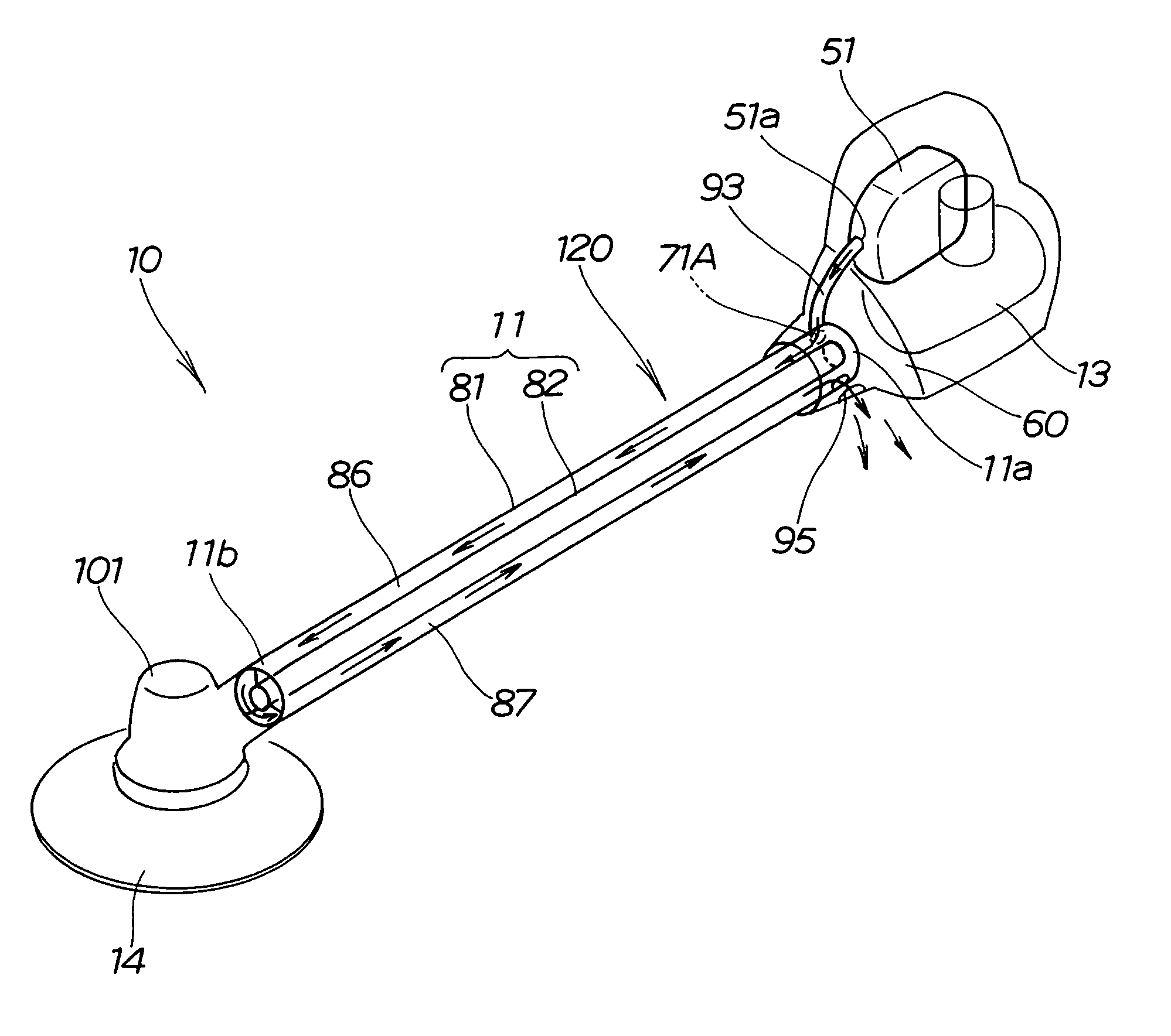
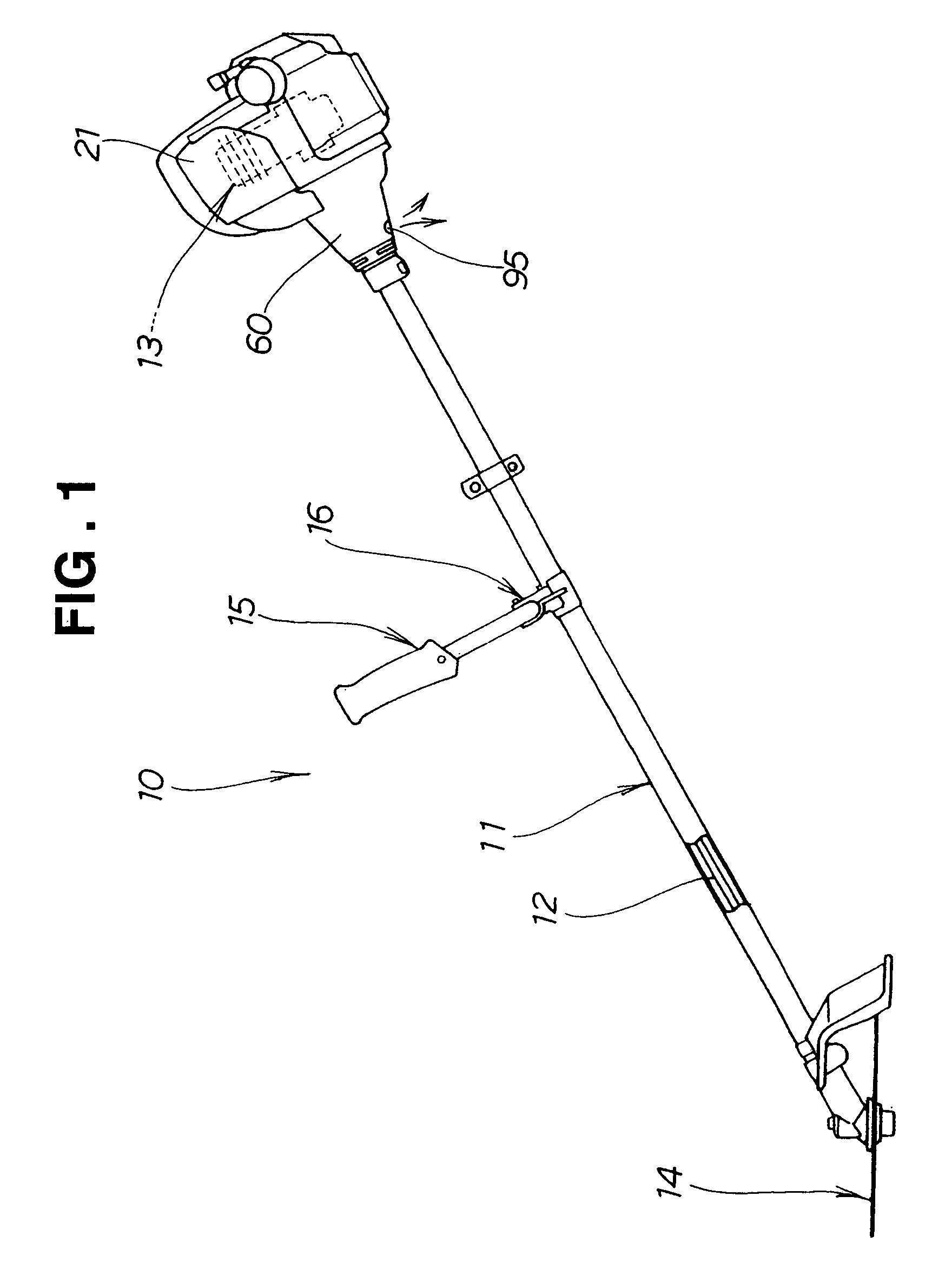
[0029]A bush cutting machine 10 shown in FIGS. 1 and 2 has a drive shaft 12 inserted through a tubular operating pole 11 and rotated by an engine 13 provided at a first end of the operating pole 11 to rotate a cutting blade 14 provided at a second end of the operating pole 11, thereby to cut weeds and the like.

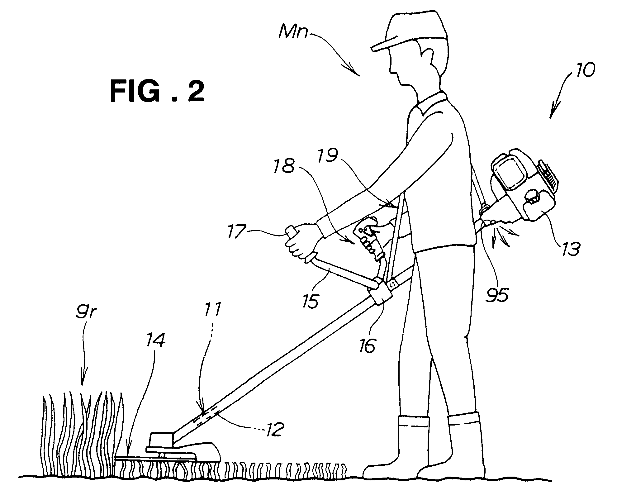
[0030]A bar-shaped handle 15 is fixed by a handle holder 16 at a longitudinally middle portion of the operating pole 11 crosswise in a plan view. As shown in FIG. 2, the handle 15 has a substantially U shape in a front view, a middle portion of which is fixed to the operating pole 11, and is made from a pipe material or a bar member extending transversely. The transversely extending handle 15 has left and right grips 17 and 18 at distal ends thereof. The right grip 18 is provided with a throttle lever and a lock lever for controlling the engine 13.

[0031]An operator Mn puts a shoulder hanging belt 19 provided at a longitudinally middle portion of the operating pole 11 on his sh...


PUM


Abstract

A bush cutting machine with a tubular operating pole connected to an outlet of an exhaust muffler and doubling as an exhaust passage is provided. Exhaust gases discharged from an engine flow from the exhaust muffler through the operating pole and are then discharged into the air. The substantial capacity of the exhaust muffler is increased by the operating pole, and the exhaust noise of the engine is reduced.

Description

FIELD OF THE INVENTION[0001]The present invention relates to bush cutting machines and, more particularly, to an art in reducing the exhaust noise of an engine in a bush cutting machine.BACKGROUND OF THE INVENTION[0002]Weeds on ridges in fields, for instance, are likely to be pest nests, and thus need to be cut several times a year. This work is hard, and thus various machines have been proposed for practical use. Of those machines, bush cutting machines are widely used because of their smallness and ease of handling.[0003]A bush cutting machine has a drive shaft inserted through a tubular operating pole and rotated by an engine provided at one end of the operating pole to rotate a cutting blade provided at the other end of the operating pole. An operator hangs the bush cutting machine on his shoulder, grips a bar-shaped handle provided at a middle portion of the operating pole and swings the operating pole right and left and backward and forward, thereby cutting weeds by the cuttin...

Claims


Application Information

Patent Timeline
Patent Type & Authority Patents(United States)
IPC IPC(8): B26B21/14F01N7/10A01D34/82A01D34/68A01D34/90F01N13/10
CPCA01D34/90A01D34/826B25F5/008
Inventor WARASHINA, MAKOTOSASAKI, HIDESHIUCHITANI, HIROAKI
Owner HONDA MOTOR CO LTD
Why Eureka
Try Eureka