Method for adjusting a fuel pressure

a fuel pressure and pressure technology, applied in the direction of electrical control, process and machine control, etc., can solve the problems of reducing the actual value of pressure, reducing the stress of the components and reducing the efficiency of the high pressure accumulator injection system

Inactive Publication Date: 2010-09-16
ROBERT BOSCH GMBH
View PDF6 Cites 8 Cited by
  • Summary
  • Abstract
  • Description
  • Claims
  • Application Information

AI Technical Summary

Benefits of technology

[0006]Against this background, an object of the exemplary embodiments and / or exemplary methods of the present invention is to state a method and a control unit by the use of which the stress of the components of the high pressure accumulator injection system mentioned is reduced.

Problems solved by technology

In hybrid drives, in which torque contributions of the internal combustion engine are controlled upwards and / or downwards while the motor vehicle is traveling, the problem arises that rapid change between operating points of the internal combustion engine having low load and rotational speed and operating points having high load and rotational speed, occur comparatively often.
Then, no drive power is available for the high pressure fuel pump either.
The result is that the actual value of the pressure, in the high pressure accumulator injection system, falls off.
These abrupt pressure fluctuations generate changing pressure peaks, which highly stress the components of the high pressure accumulator injection system in these travel states, and with that, limit the life expectancy and functionality of these components.

Method used


Image

  • Method for adjusting a fuel pressure
  • Method for adjusting a fuel pressure
  • Method for adjusting a fuel pressure

Examples


Embodiment Construction

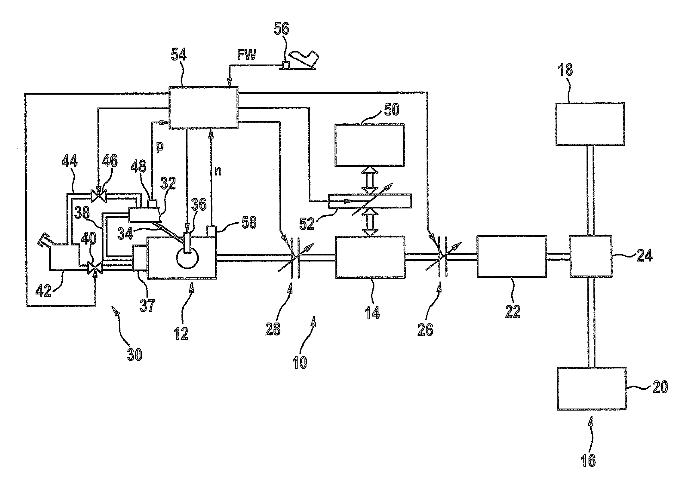
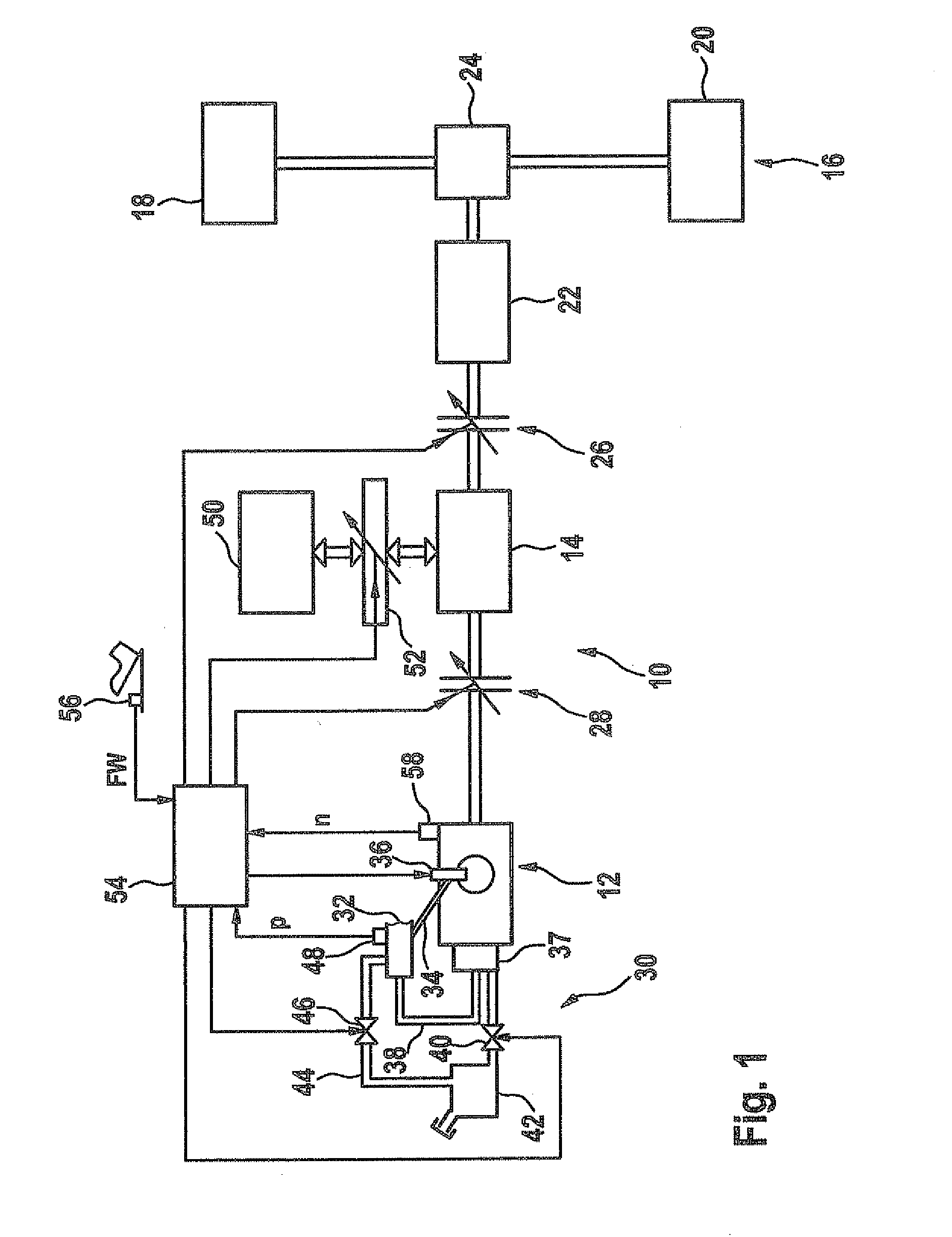
[0019]In detail, FIG. 1 shows a drive train 10 of a motor vehicle having an internal combustion engine 12 as a first drive motor and a second drive motor 14. Drive train 10 further has a drive axle 16 having drive wheels 18, 20, one or more transmissions 22, 24 and clutches 26, 28. A first clutch 26 is situated between transmission 22 and second drive motor 14, A second clutch 28 is situated between the two drive motors 12 and 14.

[0020]Internal combustion engine 12 has an accumulator injection system 30. Accumulator injection system 30 has a high pressure fuel accumulator 32, which is hydraulically connected to injectors 36 via high pressure lines 34. A high pressure pump 37 generates a fuel pressure in the high pressure fuel accumulator required for the injection of fuel via injectors 36. At its high pressure side, high pressure pump 37 is hydraulically connected via a high pressure line 38 to high pressure fuel accumulator 32. On its low pressure side, high pressure pump 37 is hyd...


PUM


Abstract

A method is provided for adjusting a fuel pressure in a high pressure fuel accumulator of an accumulator injection system of an internal combustion engine as a first drive motor which, together with a second drive motor, is situated in a drive train, in which variable torque contributions of the internal combustion engine and of the second drive motor are superposed, an actual value of the fuel pressure, which sets in in response to a lower torque contribution of the internal combustion engine in the high pressure fuel accumulator, deviating from a setpoint value specified for higher torque contributions and at which the actual value, in response to an increase in the torque contribution from the lower value to the higher torque contribution of the internal combustion engine being adjusted to its higher setpoint value. The method stands out in that the adjustment is performed so that a rate of a change in the actual value does not exceed a specified boundary value during the adjustment. A control device equipped to perform the method is also provided.

Description

FIELD OF THE INVENTION[0001]The present invention relates to a method for adjusting a fuel pressure having the features, as well as a control unit having the features.BACKGROUND INFORMATION[0002]Methods and control units of the type mentioned above are known in principle and are used in motor vehicles having a hybrid drive. Motor vehicles having hybrid drive have an electric machine, in addition to a usual internal combustion engine, which drives the motor vehicle in certain operating states alternatively or in supplementary fashion to a drive by the internal combustion engine.[0003]Modern internal combustion engines have an accumulator injection system for the fuel. The accumulator injection system is used for providing fuel having an injection pressure which is sufficient for an injection, according to demand, into the combustion chambers of the internal combustion engine. An injection according to demand requires different injection pressures depending on the load and rotational ...

Claims


Application Information

Patent Timeline
Patent Type & Authority Applications(United States)
IPC IPC(8): F02M63/00F02M59/20
CPCB60W10/02B60W10/06B60W10/08B60W20/00B60W2710/0616Y02T10/6286F02D2200/0602F02D2200/0604F02D2250/04F02D2250/31F02D41/3836Y02T10/62
Inventor HERNIER, MARKUSGREIS, ANDREAS
Owner ROBERT BOSCH GMBH
Why Eureka
Try Eureka