
Noise reducing booster insert

a technology of booster insert and noise reduction, which is applied in the field of handgun sound suppressors, can solve the problems of not providing optimal sound reduction, sound suppressor, and housing generating noise, and achieve the effect of improving the performance of a sound suppressor, facilitating the adaptation of existing sound suppressor booster designs, and increasing the sound suppression capability of a noise suppressor

Inactive Publication Date: 2011-03-15
JJE BRANDS LLC
View PDF7 Cites 33 Cited by
  • Summary
  • Abstract
  • Description
  • Claims
  • Application Information

AI Technical Summary

Benefits of technology

[0009]Accordingly, several objects and advantages of the present invention are (a) To provide an apparatus which will increase the sound suppression capability of a noise suppressor without modifying the baffle stack; (b) To provide an apparatus which improves the performance of a sound suppressor and can be easily adapted to existing sound suppressor booster designs; and (c) To provide an apparatus which, when incorporated onto the thread insert of a sound suppressor booster, will help rotationally restrain the sound suppressor while the handgun is being discharged.
[0010]Still further objects and advantages will become apparent from a consideration of the ensuing description and drawings.
[0011]In general terms the proposed apparatus is a threaded insert referred to commonly as a piston. This threaded insert when used with a sound suppressor is designed to threadedly secure the noise suppressor onto the barrel of a handgun.
[0012]Two features have been designed into the piston, but are not limited to use with the booster system which is associated with a preferred embodiment. The piston includes five vents which run parallel to t

Problems solved by technology

Some sound reduction may be gained from these designs but the noise inherent to the threaded insert being forced around inside of its housing also generates noise in its own right.
While the above represent designs which are functional for their primary purpose, to operate semi-automatic handguns, they do not provide for optimal sound reduction.
Vibration resulting from the discharge of the host weapon can cause a sound suppressor which is threadedly secured about a handgun barrel to unscrew.
This tightening works with varying degrees of success, but always leaves the potential of not being universally compatible with a variety of manufacturers' handgun barrels.

Method used


Image

  • Noise reducing booster insert
  • Noise reducing booster insert

Examples


Embodiment Construction

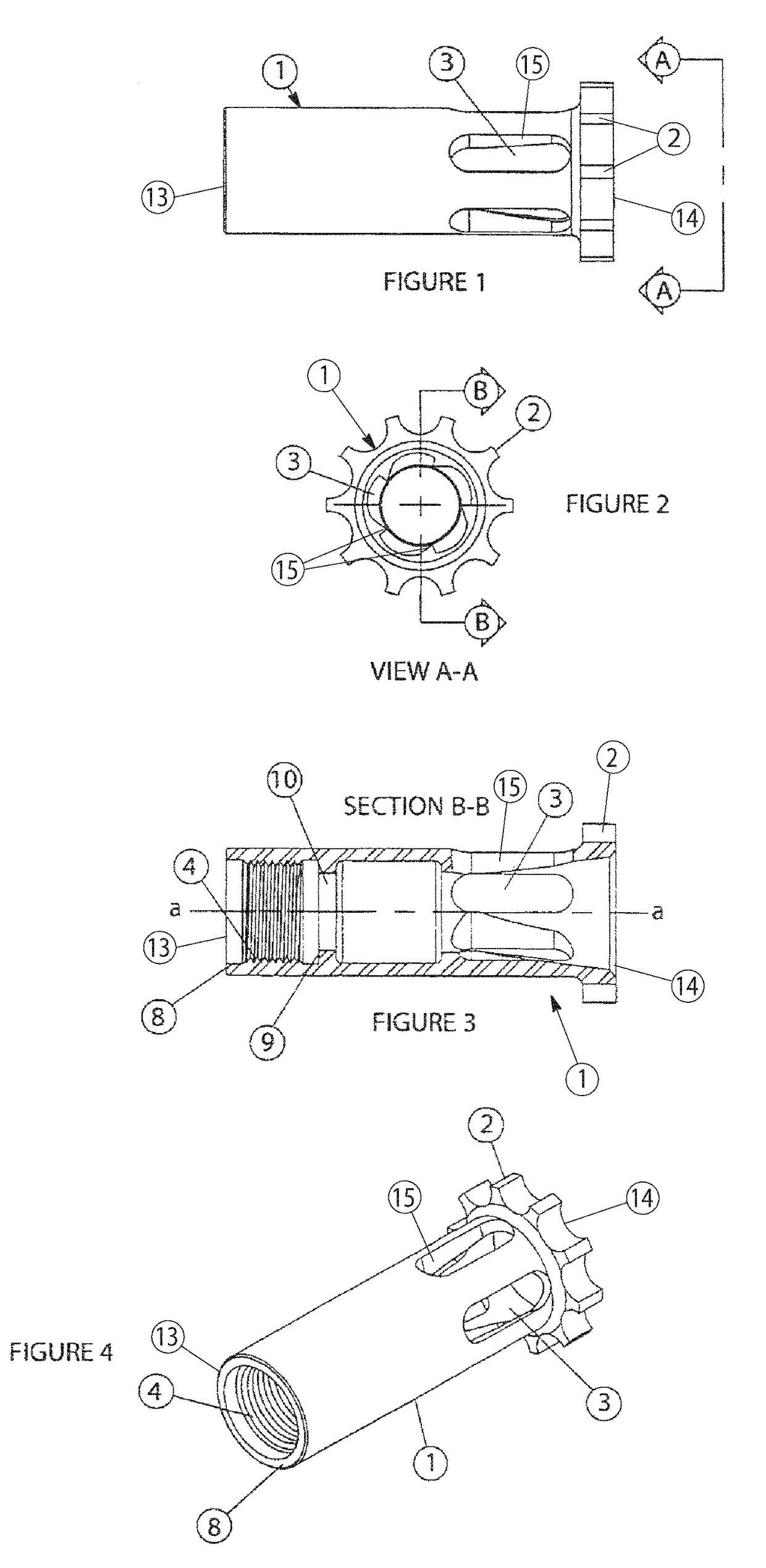
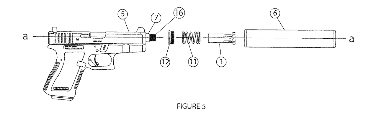
[0019]Turning now to the drawings in which like reference characters indicate corresponding elements throughout the several views, attention is directed to FIGS. 1-4, which illustrate the preferred embodiment of a noise reducing booster insert 1, hereinafter referred to as the piston 1, and FIG. 5, which illustrates the piston 1 in use with a noise suppressor and a firearm 5. As shown in FIG. 1, the piston 1 includes gas vents 3 which are machined near a front or exit end 14 of the piston 1. Ten indexing spokes 2 with notches there between are also located at the exit end 14 of the piston 1.

[0020]In FIG. 2, there is illustrated a view of the exit end 14 of the piston 1. The number of indexing spokes 2 and how they are oriented are clearly illustrated. These spokes 2 and notches allow the user to change the rotational orientation of the host noise suppressor 6 and its baffles in relation to the barrel 7 of the firearm 5. By pulling longitudinally forward on the noise suppressor 6 and...


PUM


Abstract

A noise reducing booster insert of a sound suppressor coupled to a barrel of a firearm includes an elongate body, a plurality of gas vents, and a plurality of indexing spokes. The gas vents permit expanding gases from the firearm to fill a space about the body to thereby increase noise reduction without the need of modifying a baffle stack of the sound suppressor. The gas vents are angled such that the expanding gases force the booster insert to rotate into tighter threaded engagement with the barrel of the firearm.

Description

BACKGROUND OF THE INVENTION[0001]1. Field of Invention[0002]This device relates to handgun sound suppressors, specifically to coupling attachments which are threadedly secured about a handgun barrel which are designed to aid in sound reduction when used in conjunction with a noise suppressor. Further, this device aids in the prevention of the sound suppressor from unthreading from the handgun barrel due to the incidental vibrations related to discharging the firearm.[0003]2. Prior Art[0004]There is always a need to improve the sound reduction of a sound suppressor. Generally inventors focus on improving baffle design. The device of the invention works by manipulating the expanding gases exiting a firearm prior to contact with the blast baffle.[0005]Previous systems exist for attaching a sound suppressor to a handgun barrel. Devices such as the A.S.A.P system, commercially available from Advanced Armament Corp. of Norcorss, Ga., utilize a threaded insert which rest within a cylindric...

Claims


Application Information

Patent Timeline
IPC IPC(8): F41A21/00
CPCF41A21/30
Inventor BRITTINGHAM, KEVIN TYSON
Owner JJE BRANDS LLC
Features
  • Generate Ideas
  • Intellectual Property
  • Life Sciences
  • Materials
  • Tech Scout
  • Unparalleled Data Quality
  • Higher Quality Content
  • 60% Fewer Hallucinations
Learn More