

Flame photometric detector having improved sensitivity
a photometric detector and flame technology, applied in the field of flame photometric detectors having improved sensitivity, can solve the problems of limiting the signal supplied to the photomultiplier tube, the inability to detect minute quantities of analyte,
- Summary
- Abstract
- Description
- Claims
- Application Information
AI Technical Summary
Benefits of technology
Problems solved by technology
Method used
Image

Examples
Embodiment Construction
[0015]While described below for use in detecting sulfur and phosphorous, the selective optical filter for use in a flame photometric detector can be modified to detect the presence of other elements. For example, by carefully designing the transmissive and non-transmissive wavelengths of a selective optical filter in accordance with embodiments of the invention, the presence of other elements can be detected and analyzed. Further, while particular wavelengths are described herein, the selective optical filter described below can be configured to be transmissive and non-transmissive for other wavelengths.
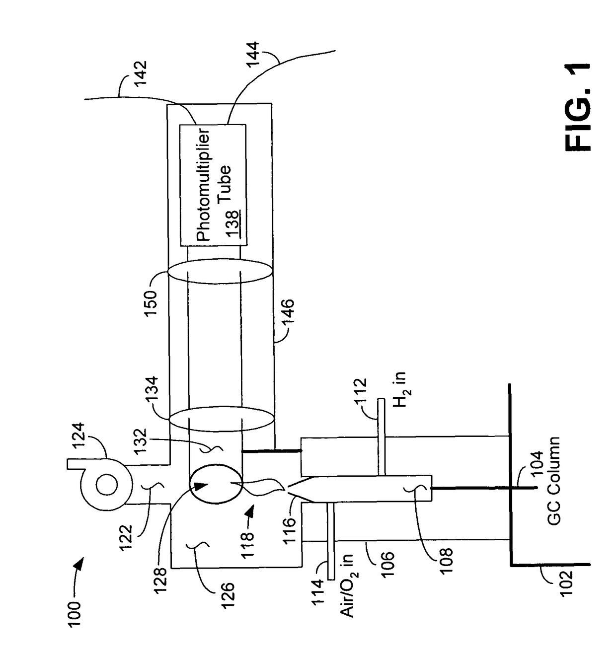
[0016]FIG. 1 is a schematic diagram illustrating a flame photometric detector 100 employing a selective optical filter. The flame photometric detector 100 generally includes a body portion 146 and a sample supply element 106. In one embodiment, the output of a gas chromatograph, illustrated at 102, including a chromatographic column 104, is supplied to an input port 108 of the sample...
PUM
| Property | Measurement | Unit |
|---|---|---|
| wavelengths | aaaaa | aaaaa |
| wavelengths | aaaaa | aaaaa |
| optical wavelengths | aaaaa | aaaaa |
Abstract
Description
Claims
Application Information