Demodulator

a demodulator and shift key technology, applied in the field of amplitude shift keying (ask) demodulators, can solve the problems of increasing the cost, difficult to improve and difficulty in improving the receiver sensitivity of the comparator

Inactive Publication Date: 2011-03-15
KK TOSHIBA
View PDF12 Cites 5 Cited by
  • Summary
  • Abstract
  • Description
  • Claims
  • Application Information

AI Technical Summary

Benefits of technology

[0009]A general architecture that implements the various features of the invention will now be described with reference to the drawings. The drawings and the associated descriptions are provided to illustrate embodiments of the invention and not to limit the scope of the invention.

Problems solved by technology

With the hysteresis function, the comparator becomes resistant to the noise; however, it is difficult to improve receiver sensitivity of the comparator.
Therefore, it is difficult to improve receiver sensitivity of the comparator.
Furthermore, a size of an element needs to be larger to reduce the DC offset voltage due to variation in the element; thus, the cost will be increased.
Therefore, a noise appears in an output of the rectifier circuit in synchronization with the clock signal.
To suppress the noise that is synchronized with the clock signal, a time constant of the rectifier circuit output needs to be larger, and it becomes therefore difficult to improve a data rate.

Method used


Image

  • Demodulator
  • Demodulator
  • Demodulator

Examples


first embodiment

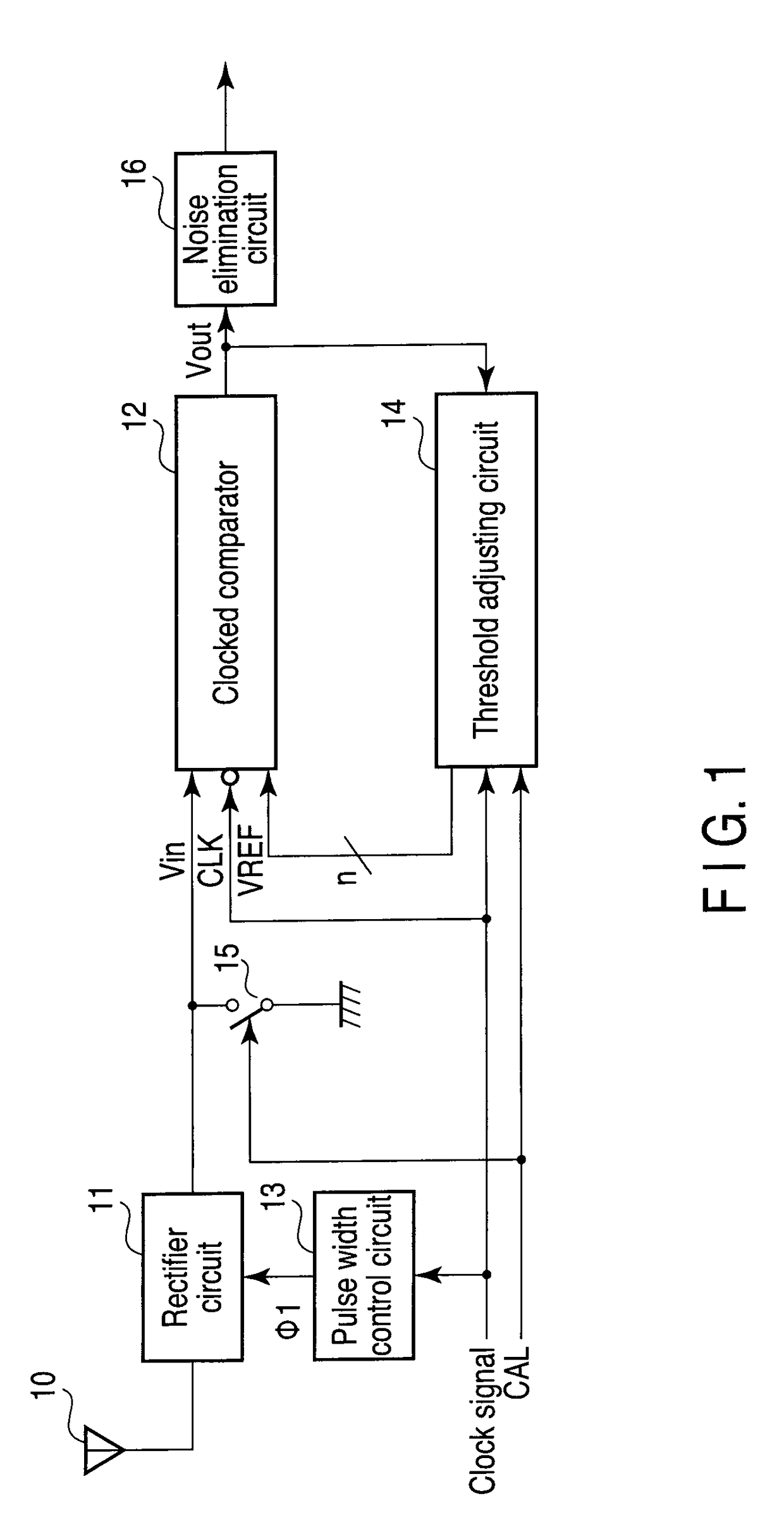
[0024]FIG. 1 is an exemplary view showing an example of a configuration of an amplitude shift keying (ASK) demodulator circuit according to the first embodiment of the present invention.

[0025]A signal from an antenna 10 is supplied to a clocked comparator 12 via a rectifier circuit 11. An output from the clocked comparator 12 is output via a noise elimination circuit 16. A predetermined bias voltage which is set for the rectifier circuit 11 is supplied in synchronization with a clock pulse φ1. The clock pulse φ1 is output from a pulse width control circuit 13 to which a clock signal CLK is supplied. The clock signal CLK is also supplied to the clocked comparator 12 and a threshold adjusting circuit 14. An output Vout from the clocked comparator 12 is input to the threshold adjusting circuit 14. The threshold adjusting circuit 14 supplies a threshold adjusting signal VREF, which is an n-bit digital signal, to the clocked comparator 12. An input terminal of the clocked comparator 12 i...

second embodiment

[0072]A second embodiment of the ASK demodulator circuit according to the present invention will be explained.

[0073]FIG. 11 is an exemplary block diagram showing an example of a configuration of an ASK demodulator circuit according to the second embodiment.

[0074]The ASK demodulator circuit shown in FIG. 11 comprises a rectifier circuit 11, a clocked comparator 12, a pulse width control circuit 13, a threshold adjusting circuit 14, a switch 15, and a noise elimination circuit 16, similarly to the ASK demodulator circuit shown in FIG. 1. The ASK demodulator circuit according to the present embodiment further comprises a digital-to-analog conversion circuit (DAC) 17. A threshold adjusting signal VREF which is a digital output from the threshold adjusting circuit 14 is supplied to the clocked comparator 12 via the DAC 17 as an analog adjusting voltage Vref.

[0075]FIG. 12 is an exemplary view showing an example of a circuit configuration of a dynamic latch 20 according to the second embod...


PUM


Abstract

According to one embodiment, a threshold adjusting apparatus for a clocked comparator, the clocked comparator comparing an input signal with a threshold in accordance with a clock, the threshold adjusting apparatus comprises an output detection module configured to detect an output from the clocked comparator with the threshold while changing the threshold and a setting module configured to set the threshold when the output detection module detects a change in the output from the clocked comparator as an adjusted threshold.

Description

CROSS-REFERENCE TO RELATED APPLICATIONS[0001]This application is based upon and claims the benefit of priority from Japanese Patent Application No. 2008-151830, filed Jun. 10, 2008, the entire contents of which are incorporated herein by reference.BACKGROUND[0002]1. Field[0003]One embodiment of the invention relates to an amplitude shift keying (ASK) demodulator.[0004]2. Description of the Related Art[0005]An ASK demodulator circuit for demodulating an ASK-modulated input signal generally comprises a rectifier circuit and a comparator. The rectifier circuit rectifies and detects a signal received with an antenna, and produces a demodulated signal. This demodulated signal is compared with a threshold by a comparator, amplified to a logical level and thereby converted to a binary signal. The comparator is often provided with a hysteresis function to suppress an error resulting from noise. With the hysteresis function, the comparator becomes resistant to the noise; however, it is diffi...

Claims


Application Information

Patent Timeline
Patent Type & Authority Patents(United States)
IPC IPC(8): H03D1/06H03D1/08
CPCH04L27/06
Inventor IWATA, SHIGEYASUYAMAMOTO, TOSHIFUMIMINEMURA, TAKASHIUMEDA, TOSHIYUKI
Owner KK TOSHIBA
Why Eureka
Try Eureka