Portable terminal apparatus

a terminal and portable technology, applied in the direction of electrical equipment, antenna details, antennas, etc., can solve the problems of deteriorating antenna characteristics of respective antenna elements, unable to perform portable wireless communication, and event may occur, so as to achieve the deterioration of antenna characteristics of respective antennas

Inactive Publication Date: 2011-03-15
PANASONIC CORP
View PDF12 Cites 84 Cited by
  • Summary
  • Abstract
  • Description
  • Claims
  • Application Information

AI Technical Summary

Benefits of technology

[0025]Even when the portable terminal apparatus of the present invention simultaneously performs the plurality of wireless communication functions by utilizing the plurality of antennas, the portable terminal apparatus can reduce that the antenna characteristics of the respective antennas are deteriorated due to the antenna coupling.

Problems solved by technology

However, when wireless communications are carried out at the same timing by employing a plurality of broadband antenna elements, such an event may occur.
That is, antenna characteristics of the respective antenna elements are deteriorated due to antenna coupling phenomena, for instance, wireless electromagnetic waves having such a frequency range which should be received by a certain antenna element are also received by another antenna element.
However, the second antenna element of this wireless appliance structure does not perform a portable wireless communication.

Method used


Image

  • Portable terminal apparatus
  • Portable terminal apparatus
  • Portable terminal apparatus

Examples


first embodiment

Mode

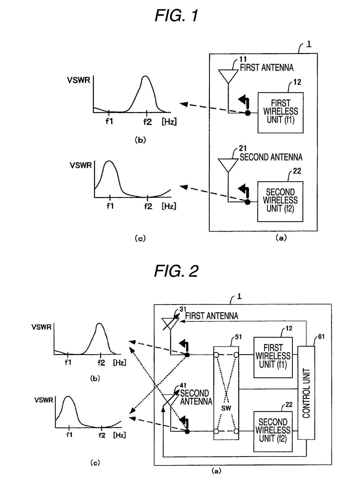
[0049]A portable terminal apparatus according to a first embodiment mode of the present invention will now be described with reference to a structural diagram (right side of drawing) of the portable terminal apparatus according to the first embodiment mode of the present invention shown in FIG. 1(a), and VSWR (Voltage Standing-wave Ratio) characteristics indicated in FIG. 1(b) and FIG. 1(c).

[0050]As shown in FIG. 1(a), the portable terminal apparatus 1 according to the first embodiment mode of the present invention is arranged by containing a first antenna element 11, a second antenna element 21, a first wireless unit 12, and a second wireless unit 22.

[0051]The first wireless unit 12 and the second wireless 22 perform a wireless communication function for performing a portable wireless communication such as a telephone conversation communication and an E-mail; a wireless communication function which is utilized in a GPS system; a television function; and a wireless communication...

second embodiment

Mode

[0056]A portable terminal apparatus according to a second embodiment mode of the present invention will now be described with reference to a structural diagram (right side of drawing) of the portable terminal apparatus according to the second embodiment mode of the present invention shown in FIG. 2(a), and VSWR (Voltage Standing-wave Ratio) characteristics indicated in FIG. 2(b) and FIG. 2(c).

[0057]As shown in FIG. 2(a), the portable terminal apparatus 1 according to the second embodiment mode of the present invention is arranged by containing a first antenna element 31, a second antenna element 41, a first wireless unit 12, a second wireless unit 22, a switch 51, and a control circuit 61. It should be understood that since reference numerals shown in the second embodiment mode are identical to those which are employed in order to explain the first embodiment and are commonly used in the second embodiment mode, descriptions thereof are omitted.

[0058]The first antenna element 31 ...

third embodiment

Mode

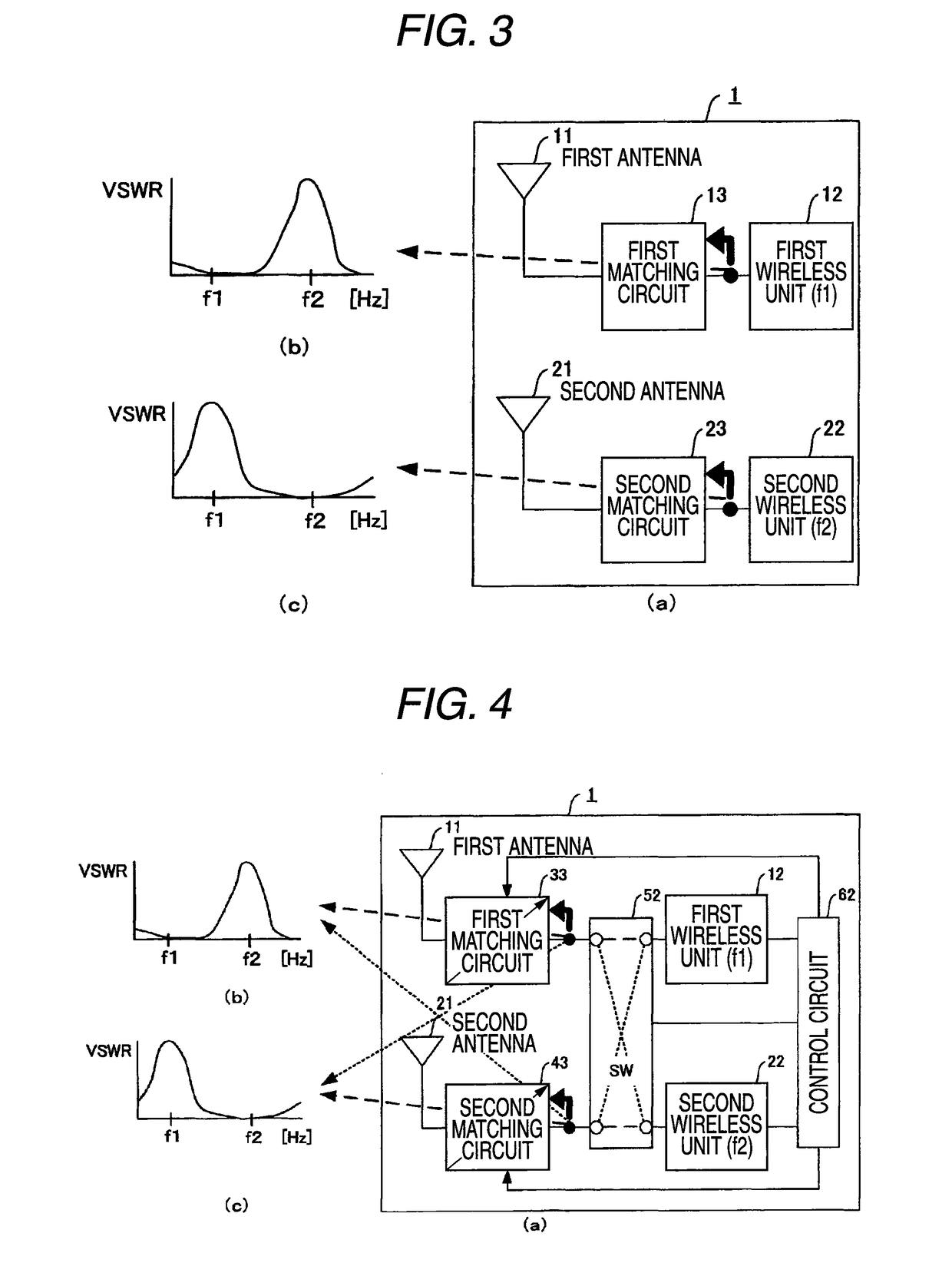
[0063]A portable terminal apparatus according to a third embodiment mode of the present invention will now be described with reference to a structural diagram (right side of drawing) of the portable terminal apparatus according to the third embodiment mode of the present invention shown in FIG. 3(a), and VSWR (Voltage Standing-wave Ratio) characteristics indicated in FIG. 3(b) and FIG. 3(c).

[0064]As shown in FIG. 3(a), the portable terminal apparatus 1 according to the third embodiment mode of the present invention is arranged by containing a first antenna element 11, a second antenna element 21, a first wireless unit 12, a second wireless unit 22, a first matching circuit 13, and a second matching circuit 23. It should be understood that since reference numerals shown in the third embodiment mode are identical to those which are employed in order to explain the first embodiment and are commonly used in the third embodiment mode, descriptions thereof are omitted.

[0065]In the por...


PUM


Abstract

The present invention has an object to provide a portable terminal apparatus capable of reducing that antenna characteristics of respective antenna elements are deteriorated due to antenna coupling phenomena even when a plurality of wireless communication functions are carried out at the same time by utilizing a plurality of antennas.The portable terminal apparatus 1 of the present invention is comprised of: a first wireless unit 12 for performing a wireless communication by utilizing electromagnetic waves of a first frequency range; a second wireless unit 22 for performing a wireless communication by utilizing electromagnetic waves of a second frequency range which is different from the first frequency range; a first antenna element 11 connected to the first wireless unit 12; and a second antenna element 21 connected to the second wireless unit 22; and in the portable terminal apparatus 1, an impedance characteristic of the first antenna element 11 has a first frequency characteristic in which at least a characteristic in the first frequency range is superior than a characteristic in the second frequency range; and an impedance characteristic of the second antenna element 21 has a second frequency characteristic in which at least a characteristic in the second frequency range is superior than a characteristic in the first frequency range.

Description

TECHNICAL FIELD[0001]The present invention is related to a portable terminal apparatus having a plurality of antennas. More specifically, the present invention is directed to such a portable terminal apparatus for simultaneously performing the plurality of wireless communication functions by utilizing the plurality of antennas.BACKGROUND ART[0002]Among recent portable terminal apparatuses such as portable telephones, certain types of portable terminal apparatuses have contained therein a plurality of antennas. These portable terminal apparatuses equipped with the plural antennas are operated to perform wireless communications in such a manner that signal reception levels of antenna elements thereof are measured, and then, the wireless communications are carried out by utilizing such an antenna element having a higher signal reception level. As a result, even when a reception characteristic of one antenna element is deteriorated, since, by utilizing another antenna element having a s...

Claims


Application Information

Patent Timeline
Patent Type & Authority Patents(United States)
IPC IPC(8): H01Q1/24H01Q3/24
CPCH04B1/0064H04B7/0805H04B7/082
Inventor KAKITSU, HARUHIKONAKANISHI, HIDEOOCHI, TAKAHIRO
Owner PANASONIC CORP
Why Eureka
Try Eureka